UPDATE FOR THE SLOW 12.19.2010 THIS IS A SOLDERLESS /PLUGGABLE VERSION OF THE REGION MOD .IT REQUIRES NO SOLDERING TO INSTALL IT.THINK SOLDERLESS ADAPTER PS2/XBOX MODCHIPS XENIUM SPICE ETC ETC
On gameSx originally
http://nfggames.com/forum2/index.php?topic=4320.0I'll get this bit out of the way first,the inevitable question that pops up from those WHO DON'T FECKIN READ ANYTHING OTHER THAN THE TITLE


WHY DO THIS WHEN YOU CAN JUST MAKE AND SOLDER THE REGION MOD IC ?
We'll you can do that ,but this is aimed at those folk who really don't want to mess about with a soldering iron ,or aren't comfortable/skilled with one and don't want to risk destroying anything with one ! So the implementation is here to show it can be done ,and hopefully it can be improved upon and made available for modders to sell to those type of people (like the solderless ps2/xbox mod chips).And there's not really a use/need for using the crimp terminals over soldering to the IC's matrix board,i used them just for the fun of it and for experimentation .
Details of the wire size ,crimp terminals etc can be found in my other guide ;
http://nfggames.com/forum2/index.php?topic=4283.0I got to the end and then found i had forgotten one MAJOR part to solve.The lifting of pin 29 and how to attach the Vss / ground wire to it without soldering the bugger .But i fixed that flaw,and i hope someone can come up with a better method though.
Also you'll notice some pictures are not in the right order,the wire around the leg/pin 29 changes from copper to silver stranded

and also the use of an old dodgy core grafx for showing lifting of leg 29 (which isn't leg 29

... ................................................................................
I'm not going through the whole thing of showing the fitting of the spdt slide switch ,cutting the matrix board ,soldering it etc etc ,for those parts, follow the links below
http://mmmonkey.co.uk/console/pce/region.htmhttp://playoffline.wordpress.com/mod/pceswitch/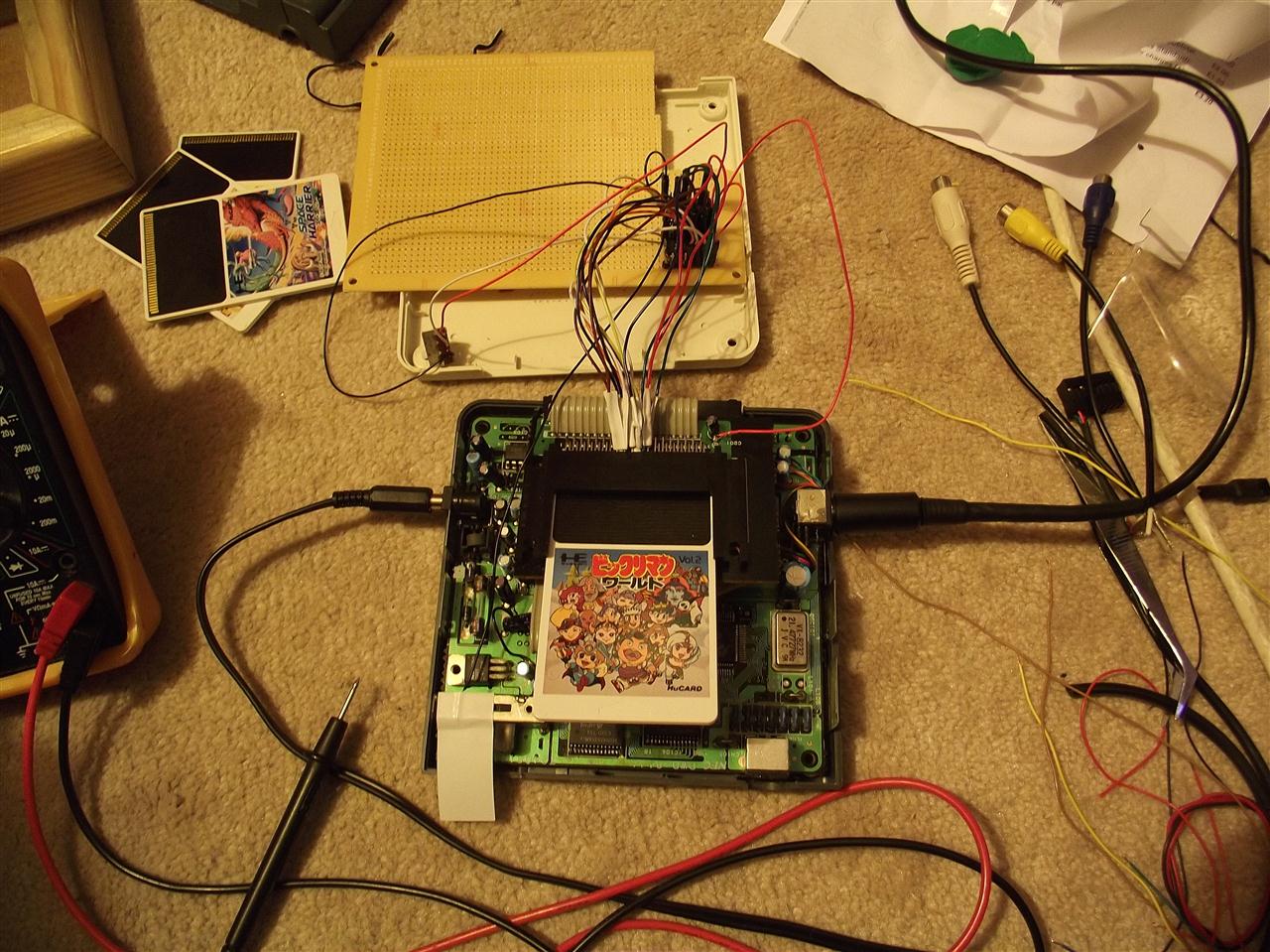
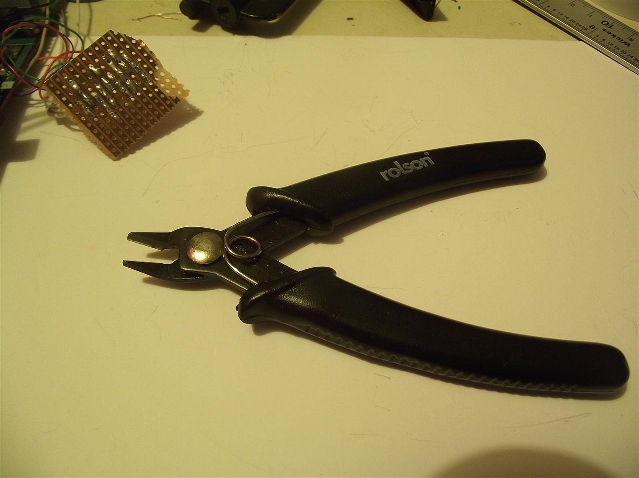
These wire cutters will fit inside the area and between the pins that have to bee snipped ,on the back of the HU card connector.
Turned Pin SIL PCB Socket 18 way
This socket has a pitch of 2.54mm
http://www.technobotsonline.com/turned-pin-sil-pcb-socket-20-way.html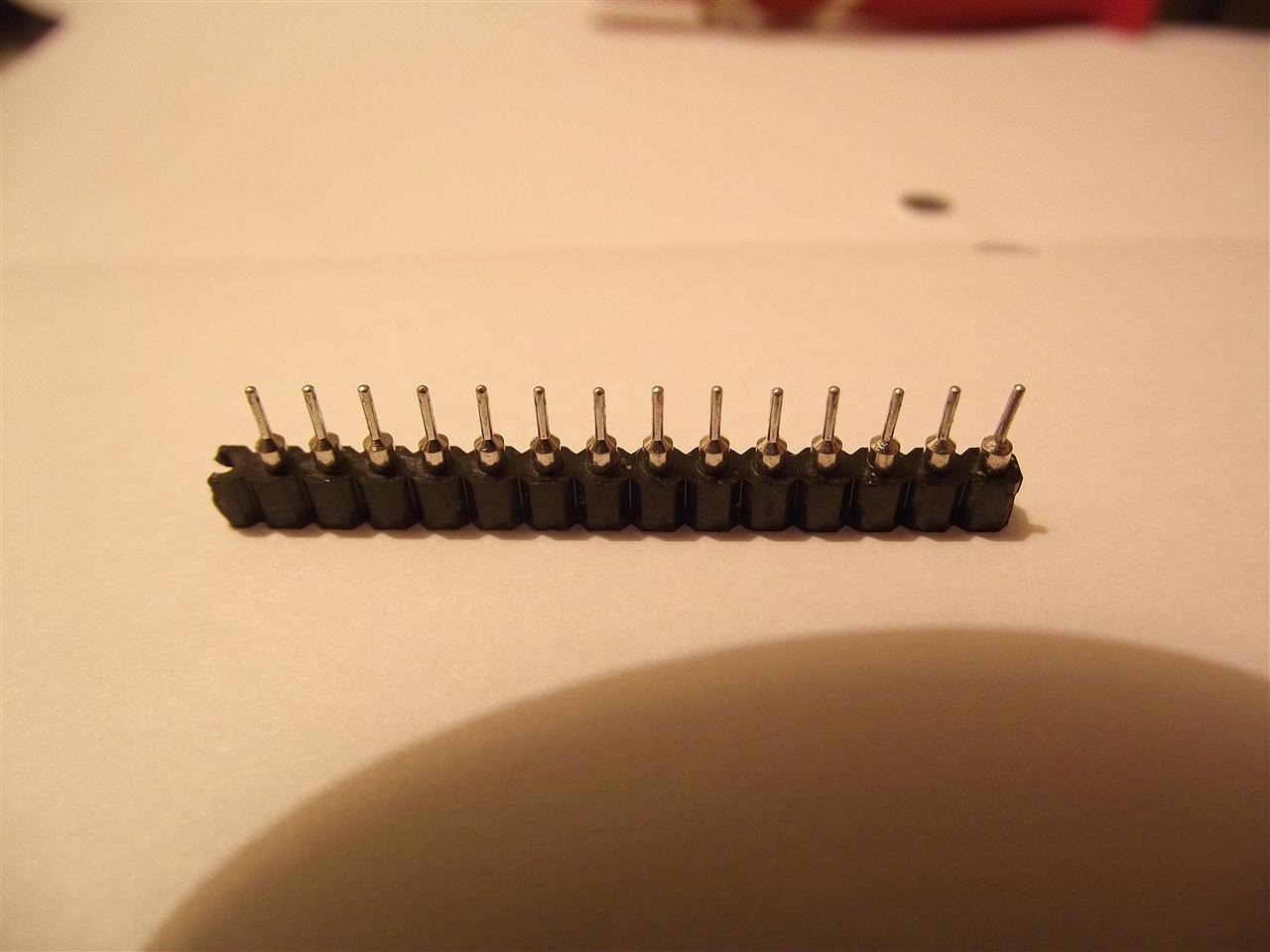
more
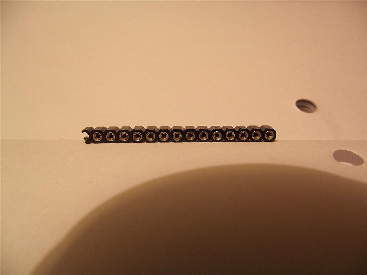
Cut the plastic of of each and all of the sockets,so you're left with bare metal.Tin the pin end!
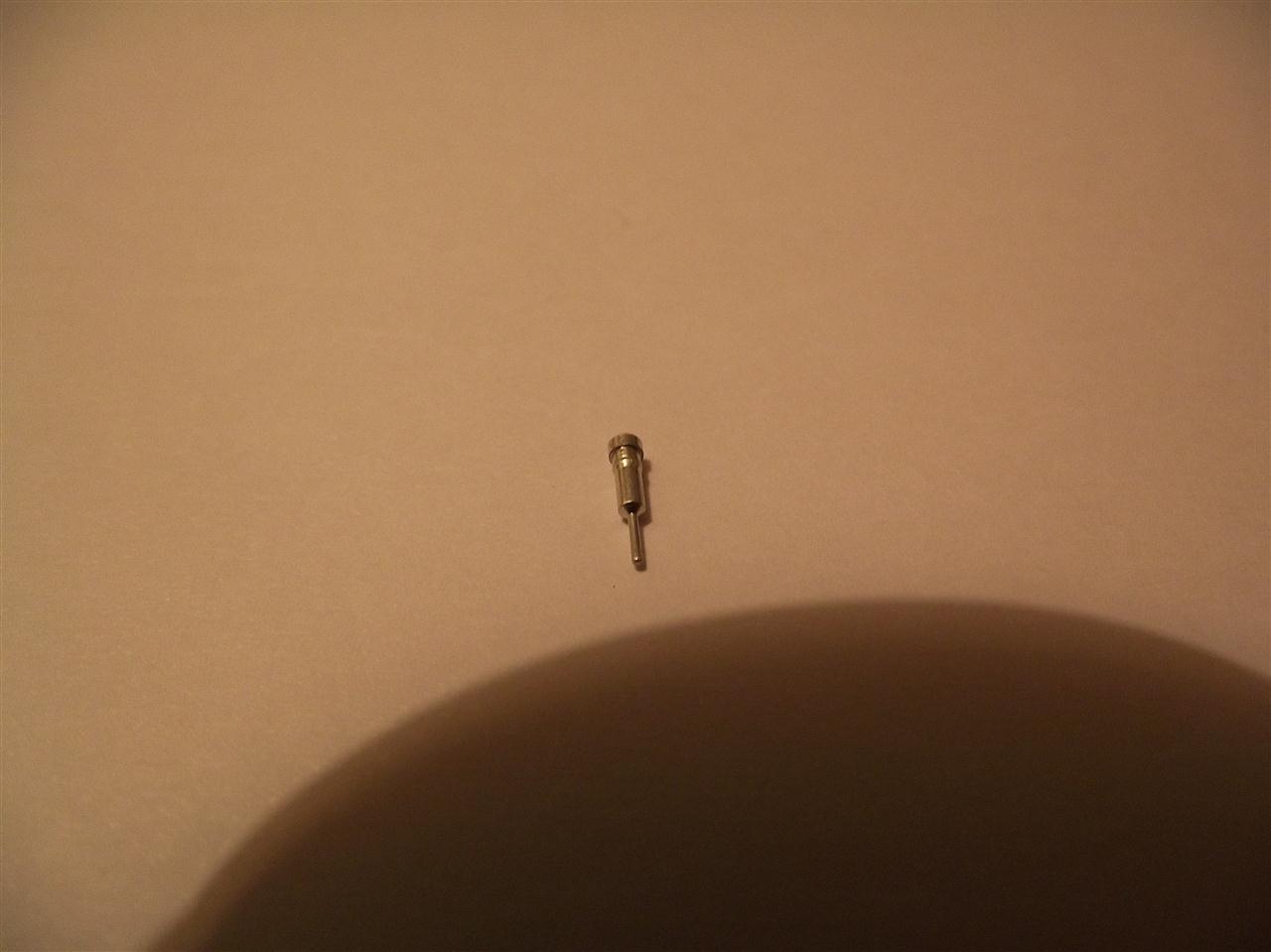
I cut my 8 core wire to this length.
16 bits for the back of the HU card connector legs/pins ,extra bits were cut for my Vcc and Vss connections on the IC and the spdt switch and the control wire going to the IC and also for leg 29 on the console's pcb IC.
I Stripped both ends ,about 3 mm ,then tinned only one end ,the end which is to be soldered to the pin end of the SIL socket.
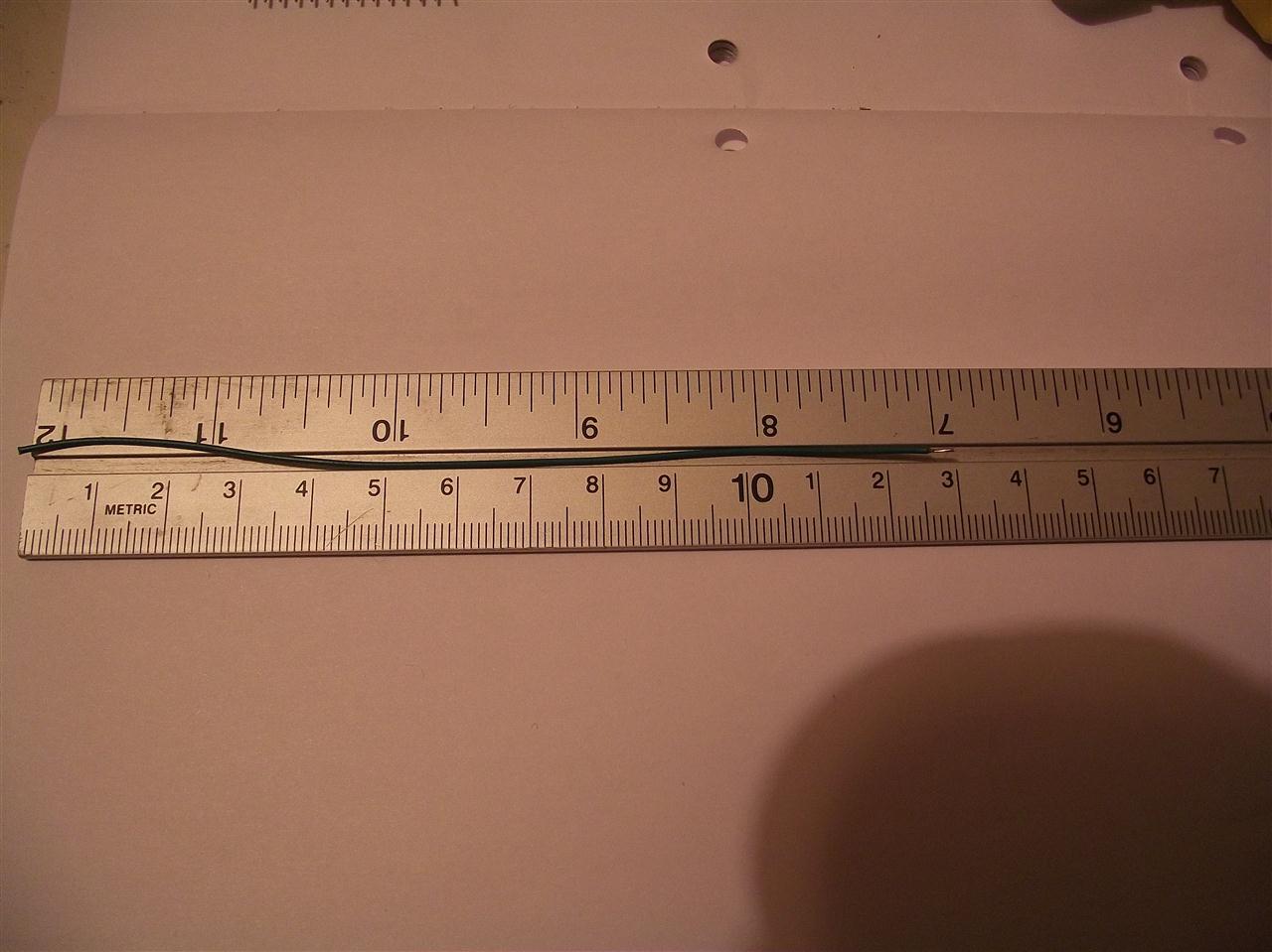
more
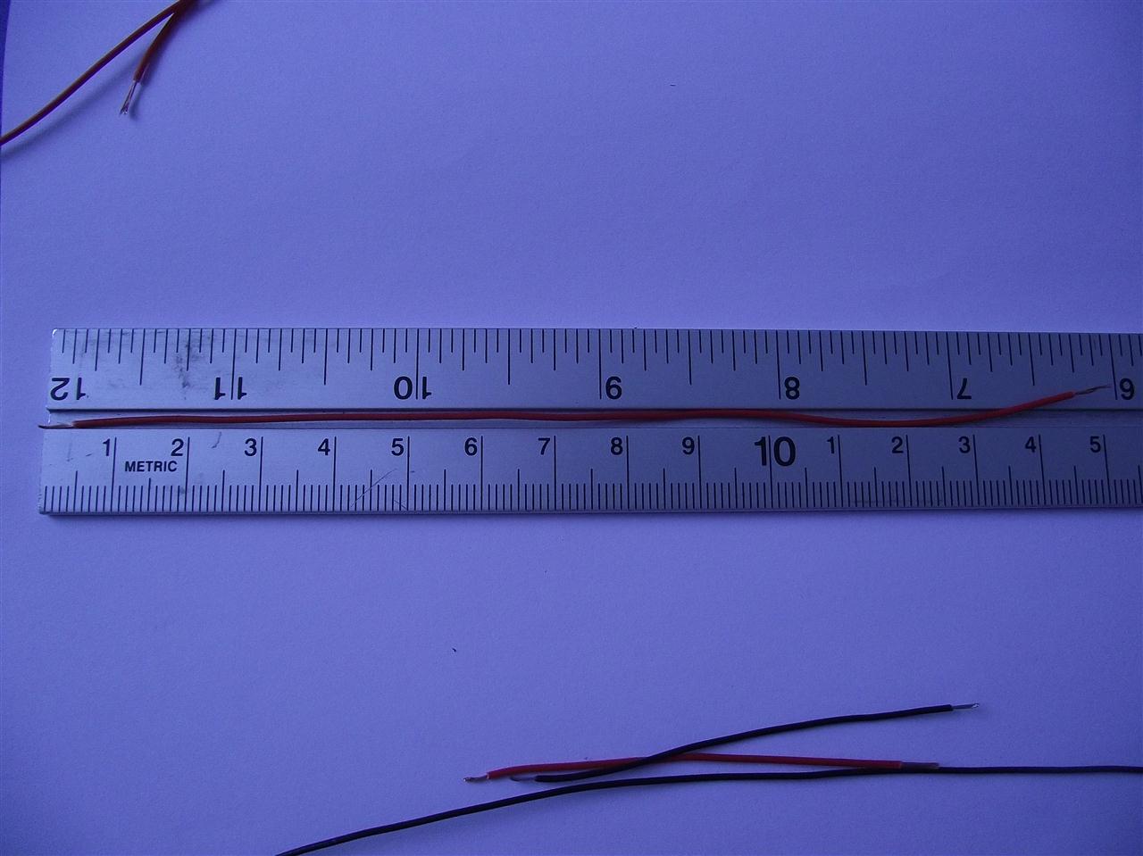
more
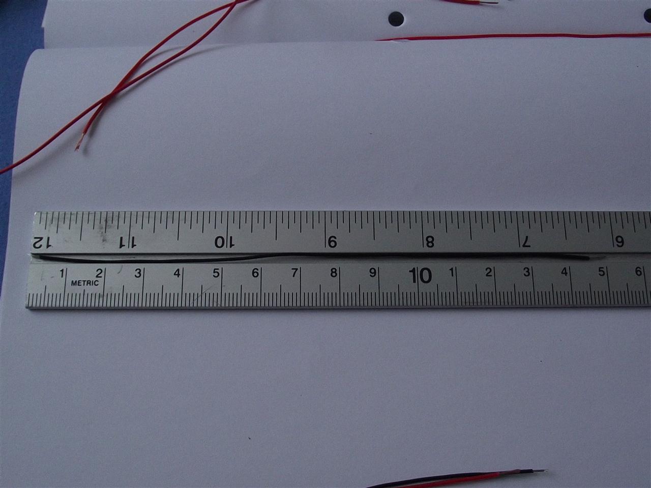
These were for my Vcc connections.
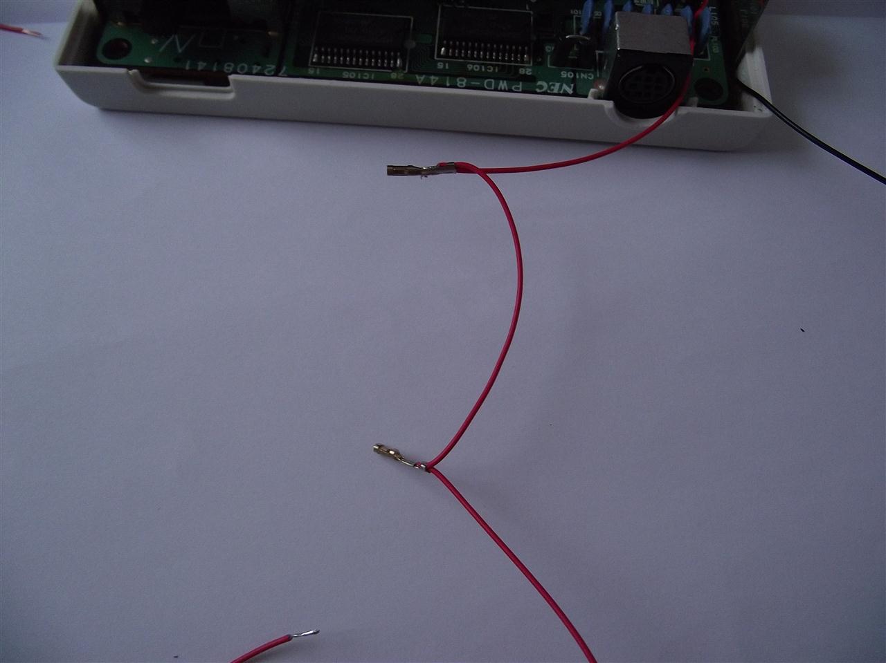
Finished Vcc and Vss connections.
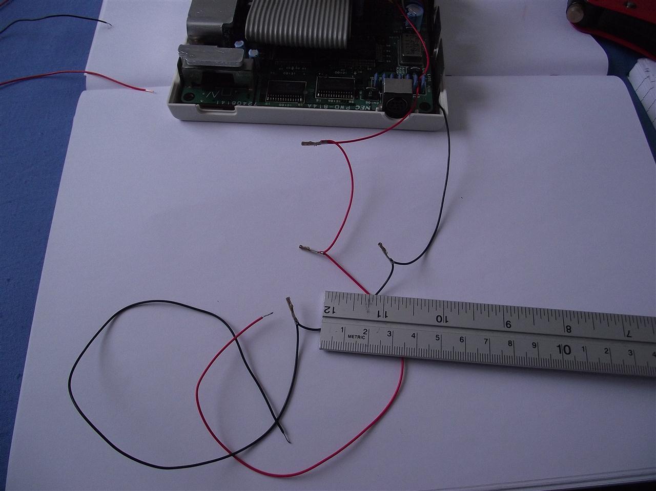
more
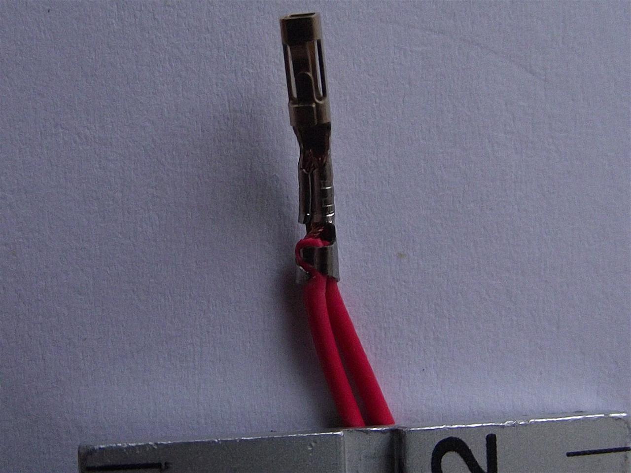
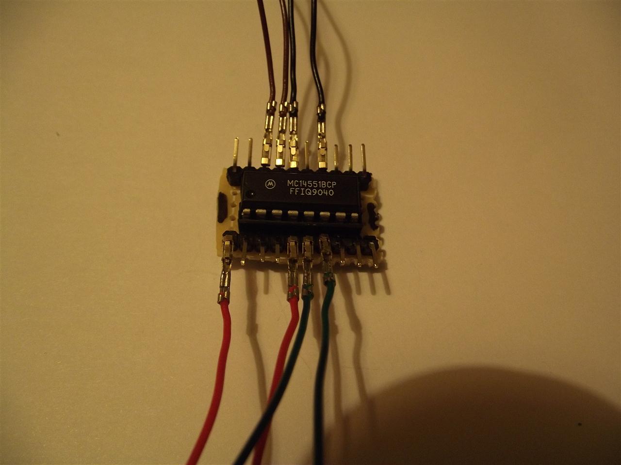
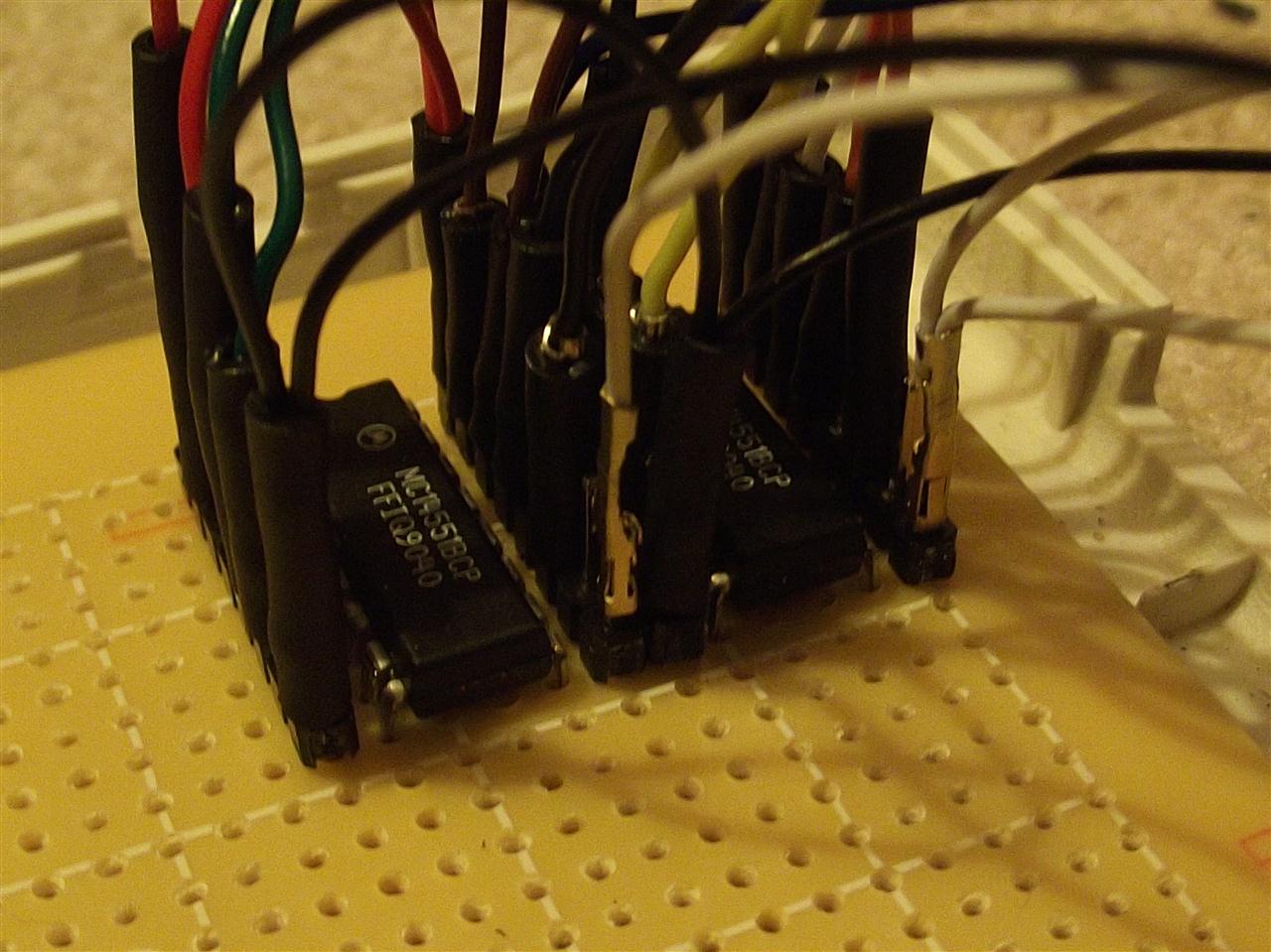
Different mock up showing basically how my crimp terminals (minus heat shrink )would connect to the IC matrix board (2.54 mm pitch pcb headers ,ic plugged into a dil ? socket (which is useless as it would create a board that is too high to fit in the console).
DO NOT TAKE THE POSITION OF THESE CUT LEGS AS THE REAL POSITION ON THE BACK OF THE HU CARD CONNECTOR,THEY ARE JUST USED AS AN AN EXAMPLE .
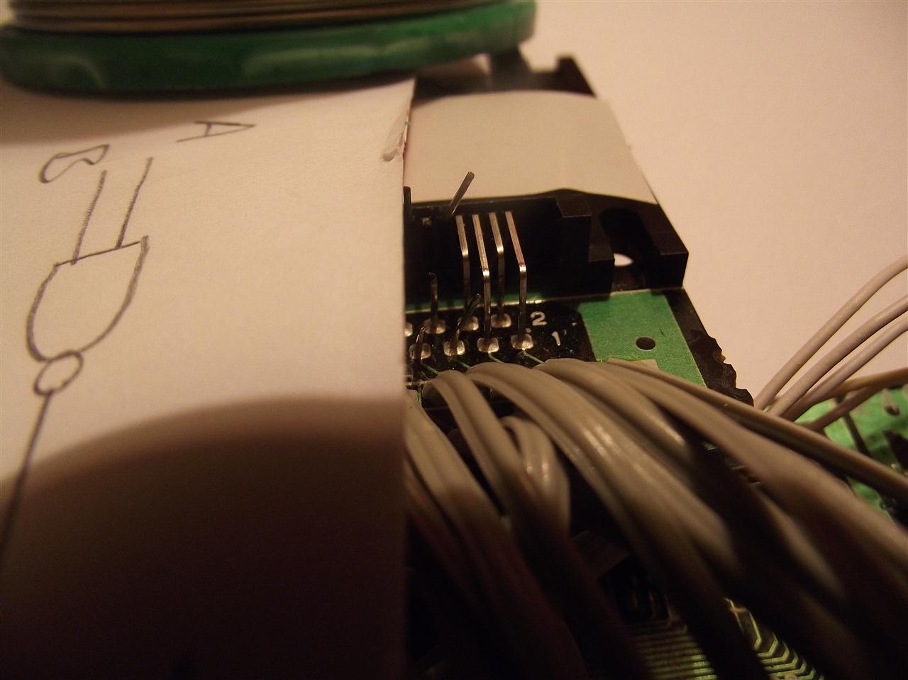
Example cuts
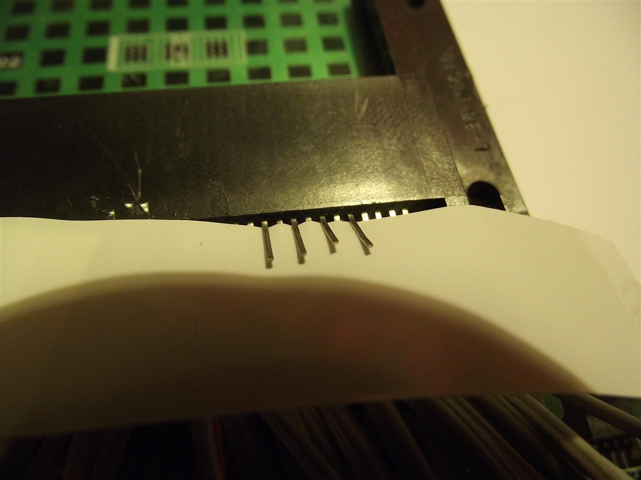
SIL socket attached minus any heat shrink
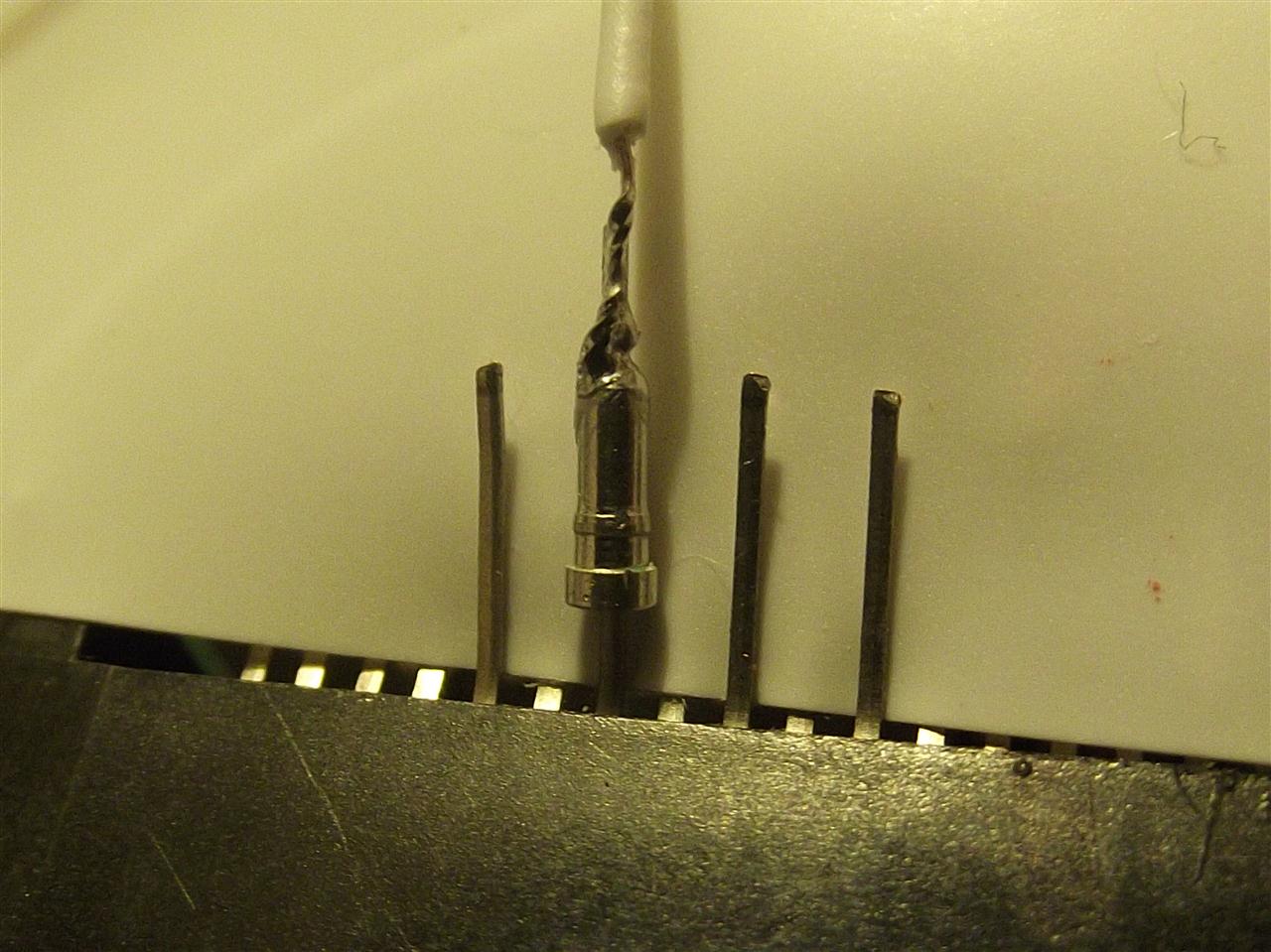
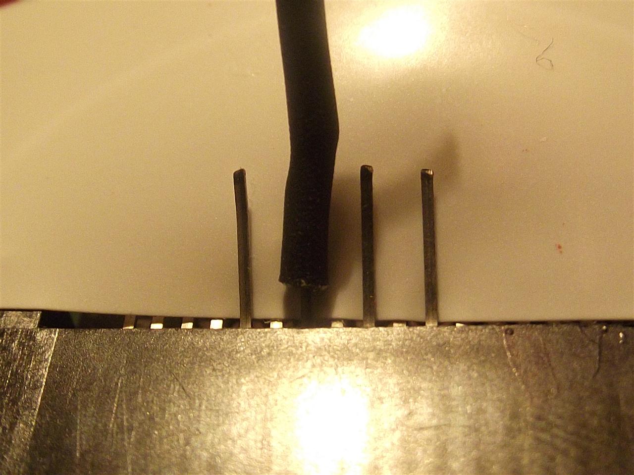
The heat shrink must just cover the end of each SIL socket ,as they have a little protruding outer lip/ring which will touch the others,as long as it's insulated (which i ran out of shrink ,so used electrician tape instead on the finished 1st picture above)
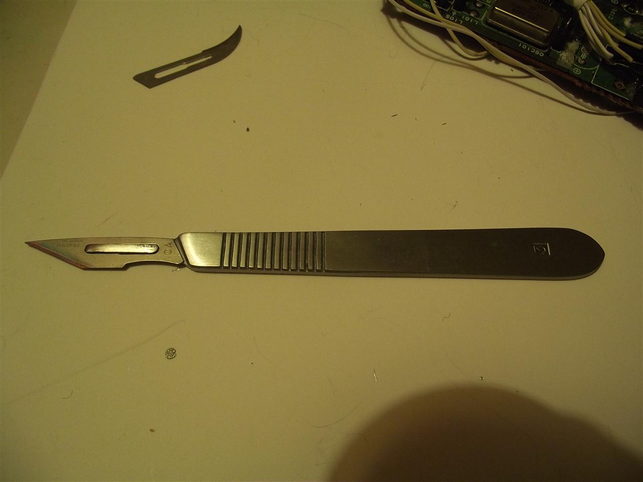
Scalpel ,used for lifting leg 29 .Number 3 handle ,with a number 10a blade.
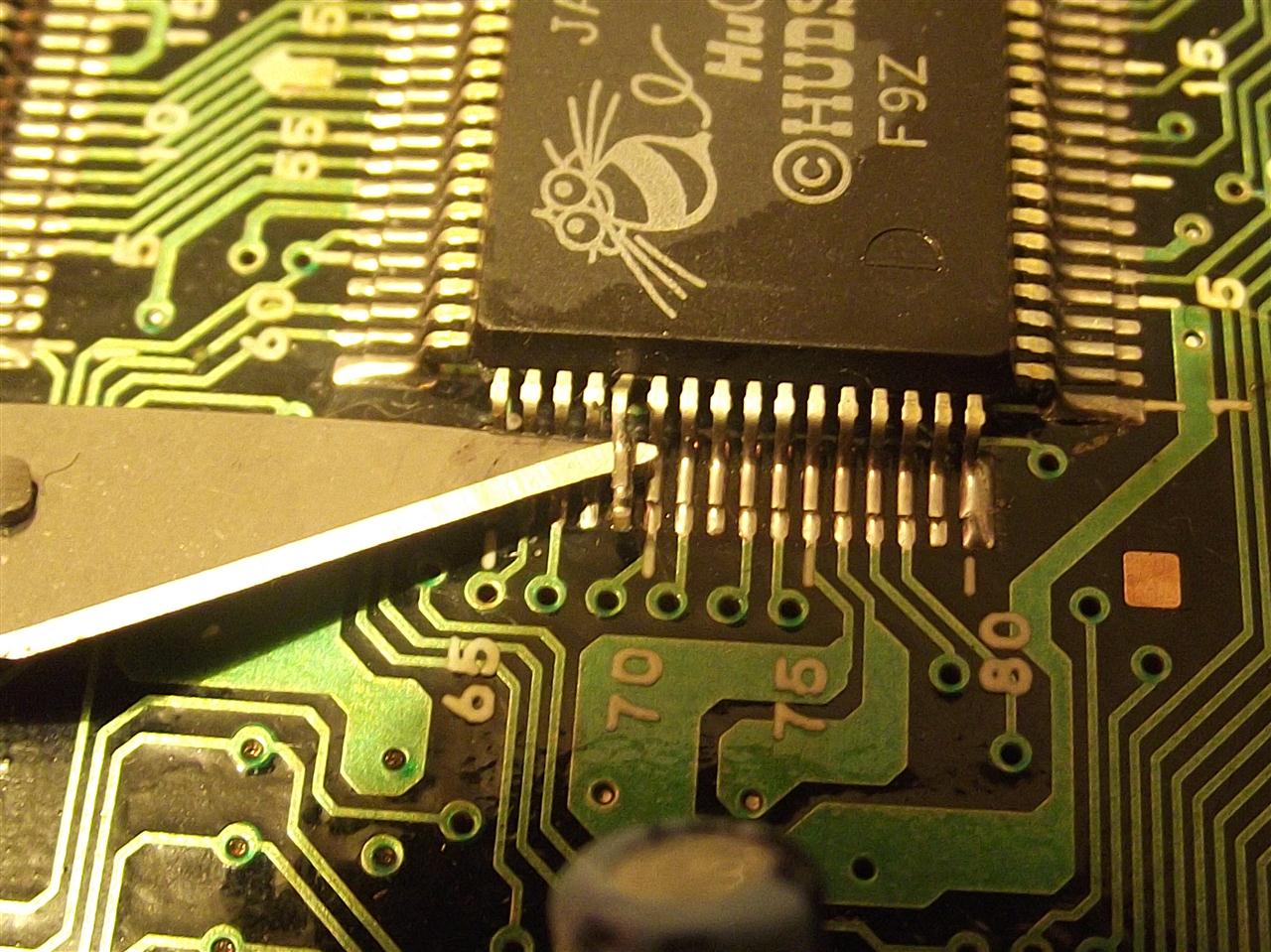
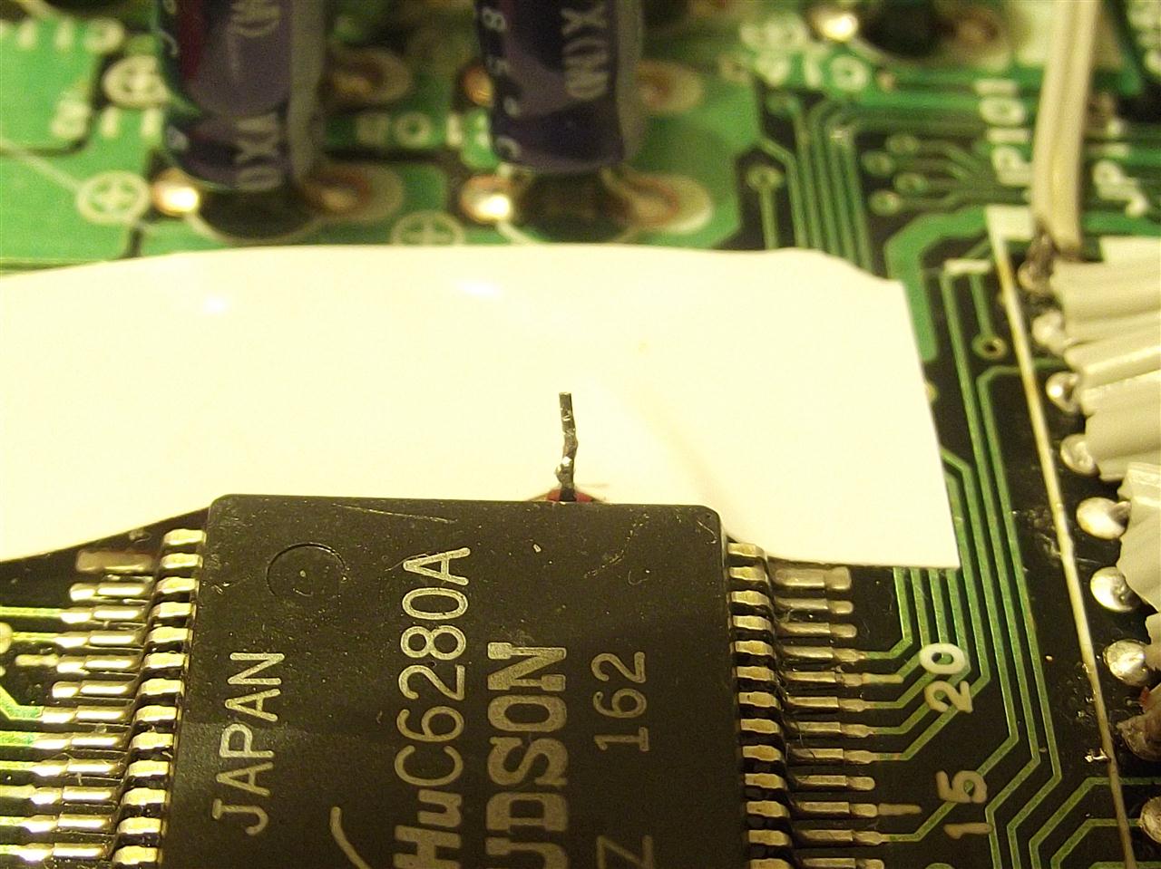
As leg 29 on the IC has no trace attached to it,making it next to no risk when you gently pry the leg up off the pcb.
Example ,used on dodgy core grafx and not the correct leg/IC .
Follow links in the first post .
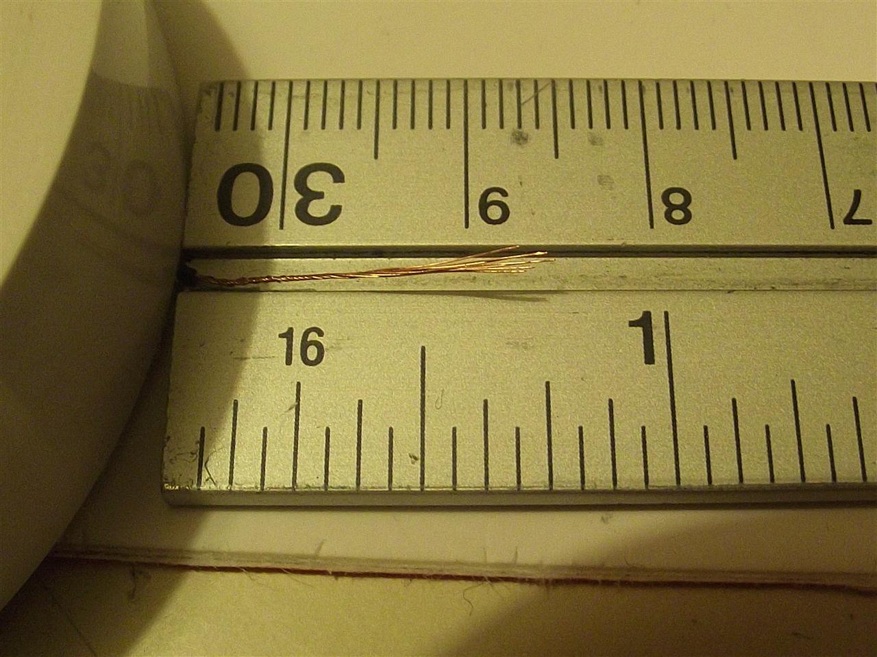
Stripped and nearly ready for attaching to leg 29
One small needle,about 1mm or 0.5 mm thick.
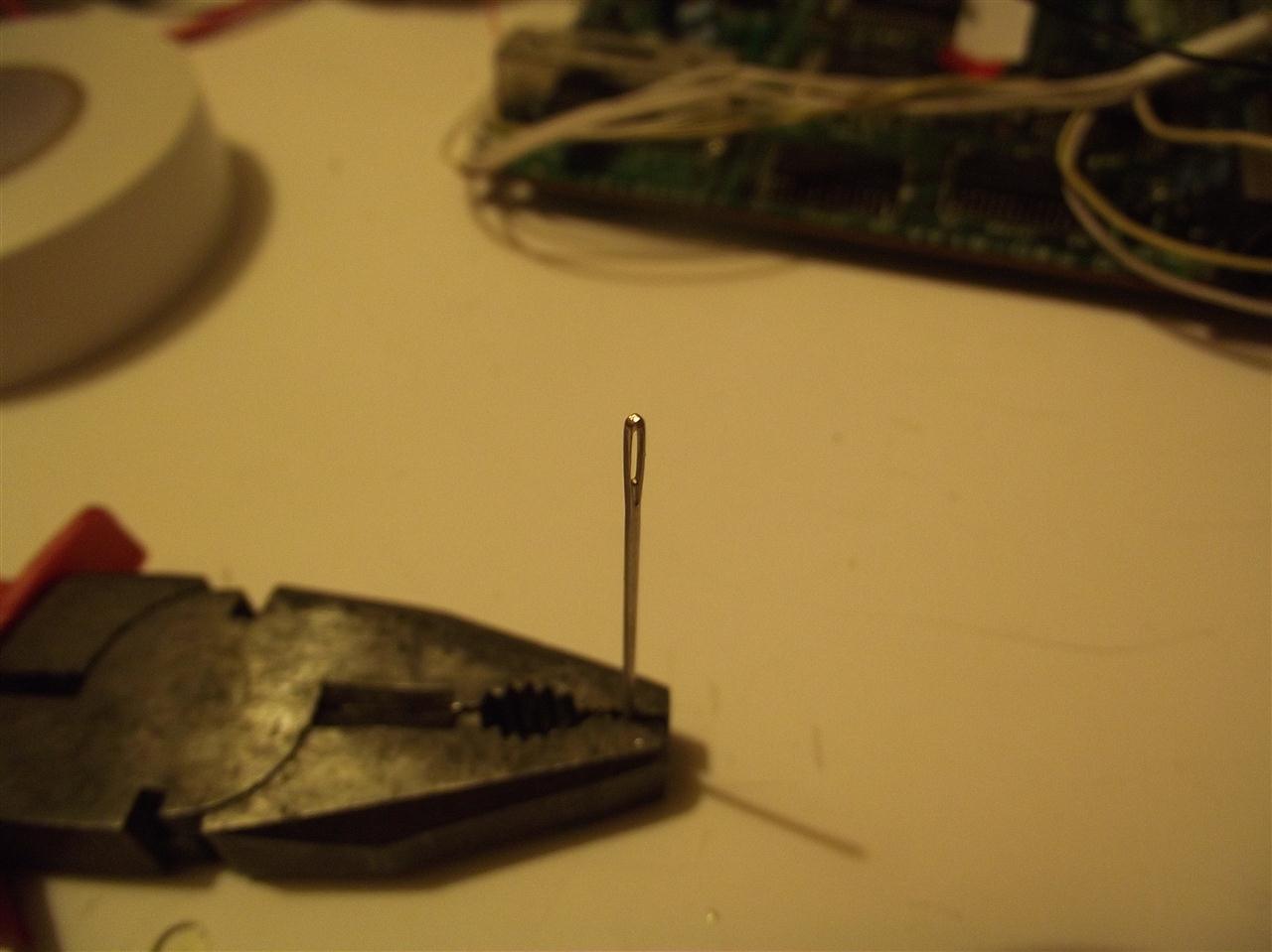
Around and around we go
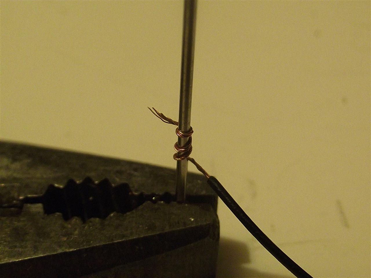
Once this is tightly wrapped enough,it will then fit over leg 29 and taped down to give a more secure fitting .
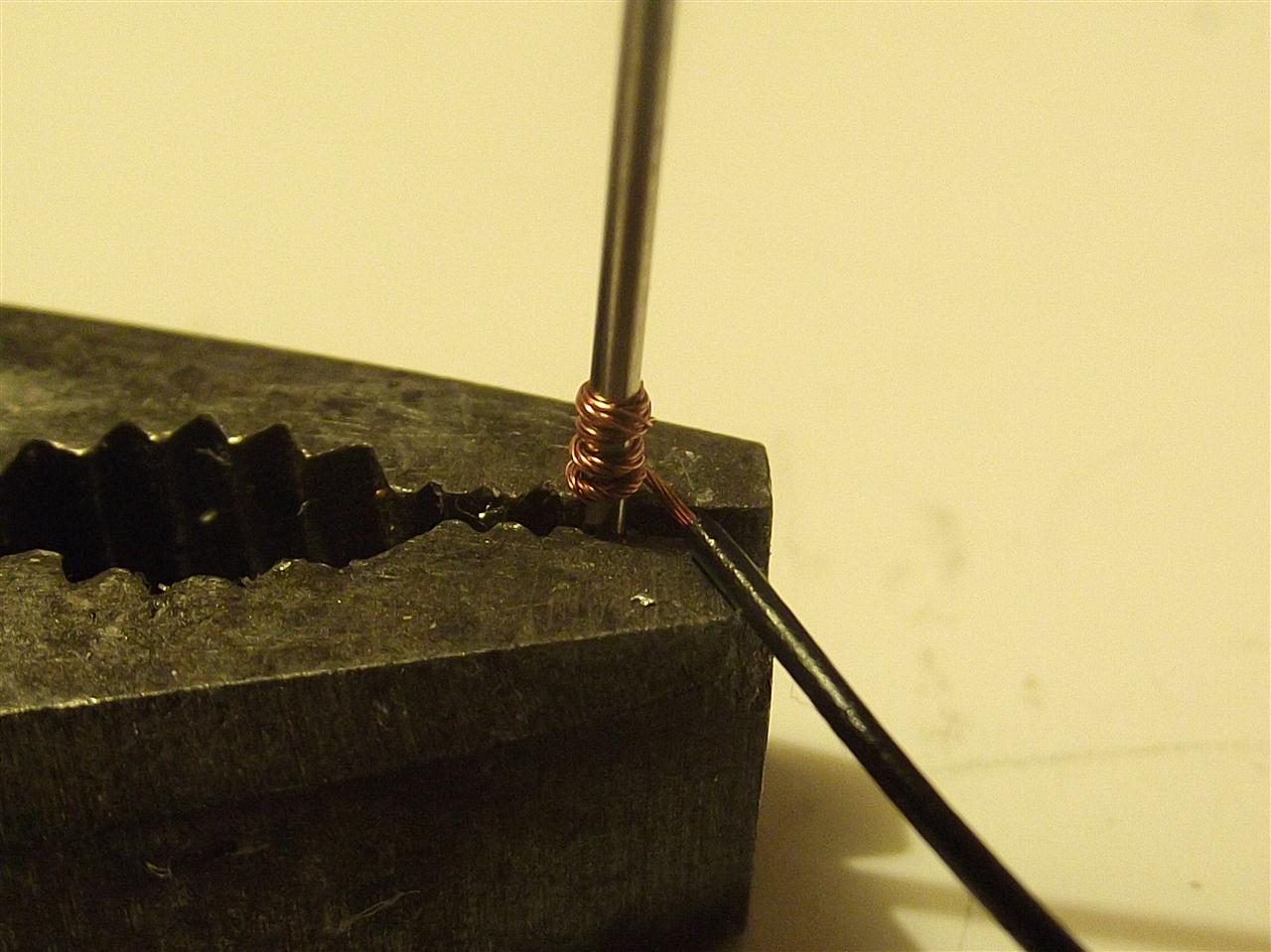
Where the needle point is is the thinnest ,so the bare wire is more tightly wrapped and a better, tighter fit around the base of the leg,the wider part of the needle wrap wire you can see showing ,doesn't pose a problem ,as it's is much tighter at the base.
Checking with a multi meter will show no faults with it.
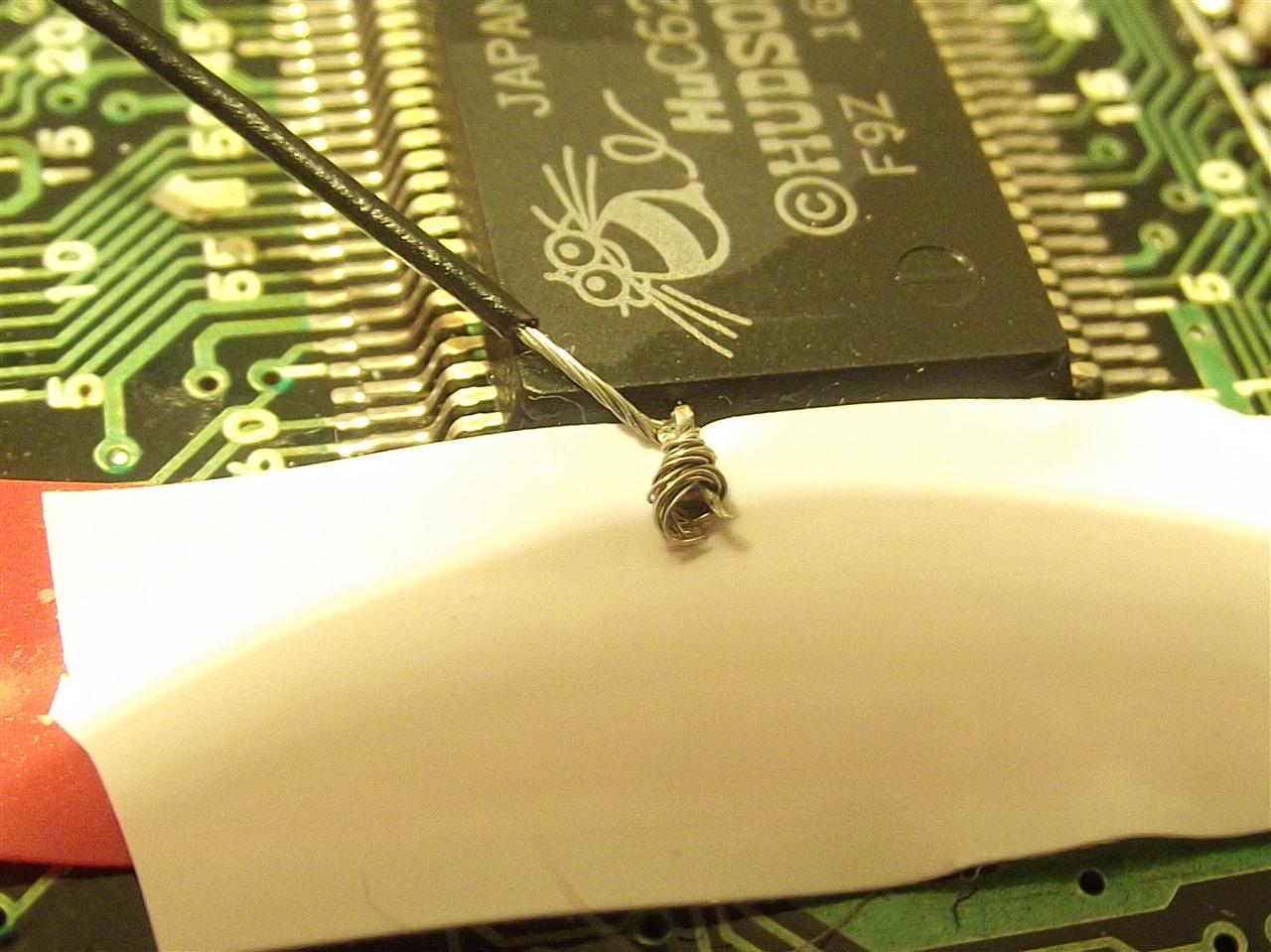
more
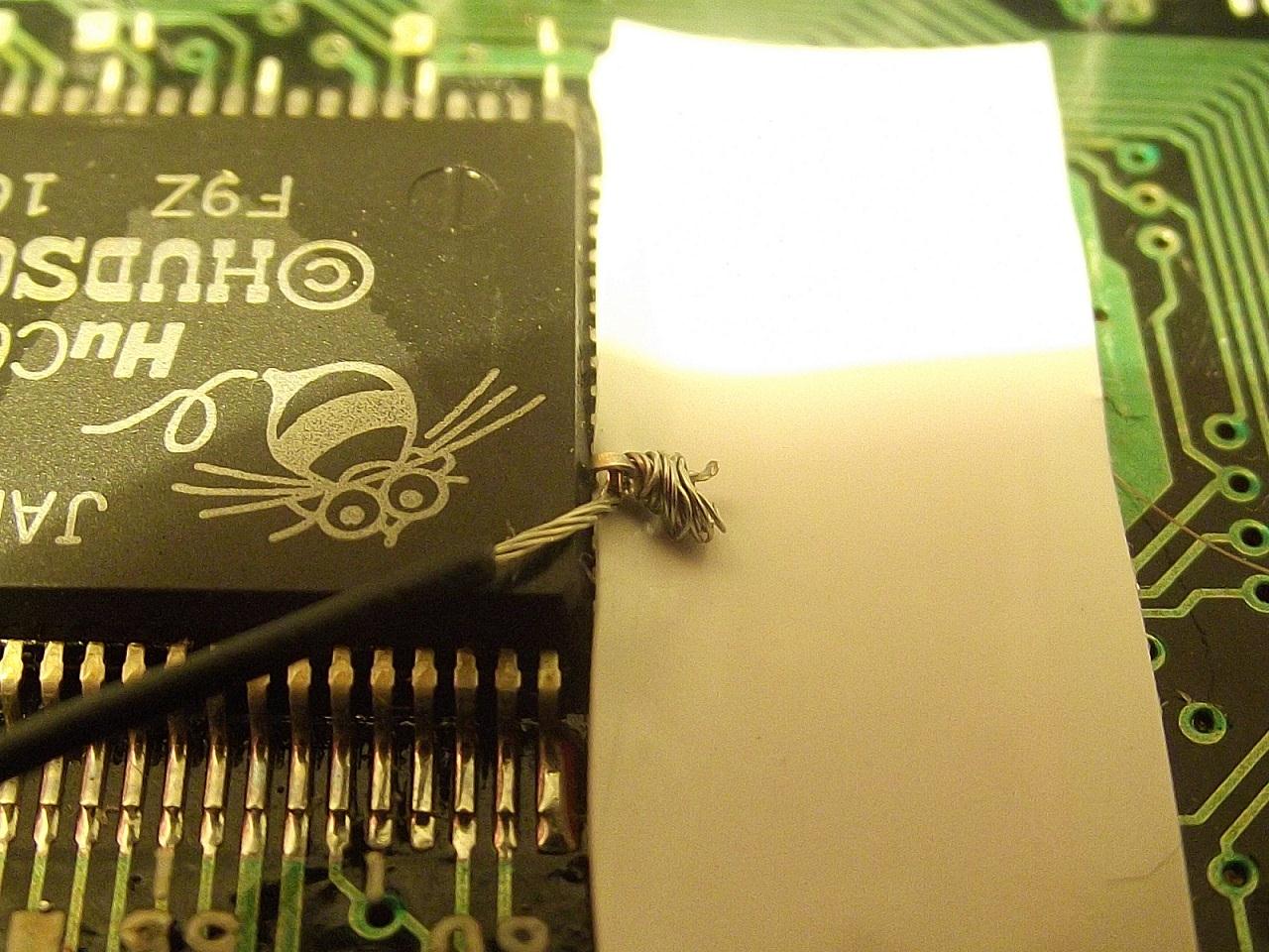
Different way to ground leg 29,using a SIL socket which is a perfect fit.Checking with your multi meter will show no problems with the connection (maybe some hot glue would add some further securing of the connection )
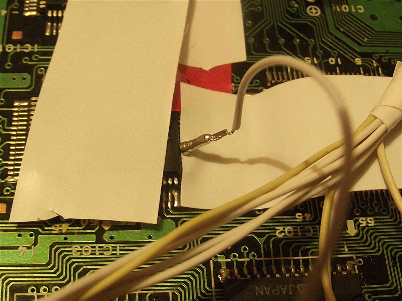
more
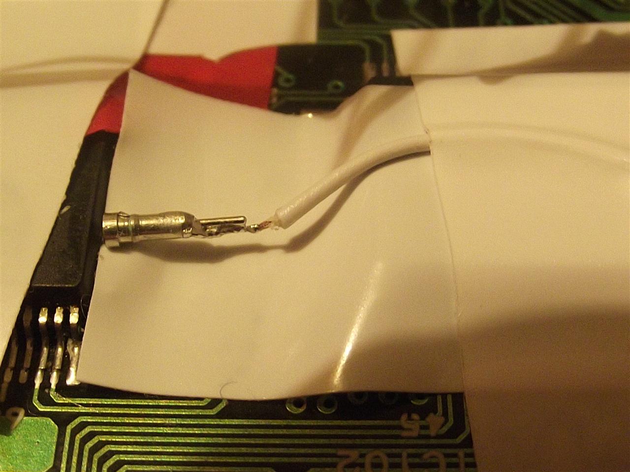
Connecting up to show that leg 29 is connected fine
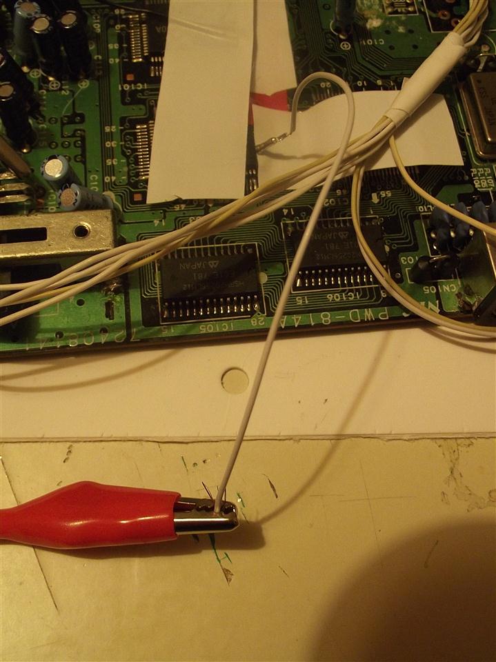
As above
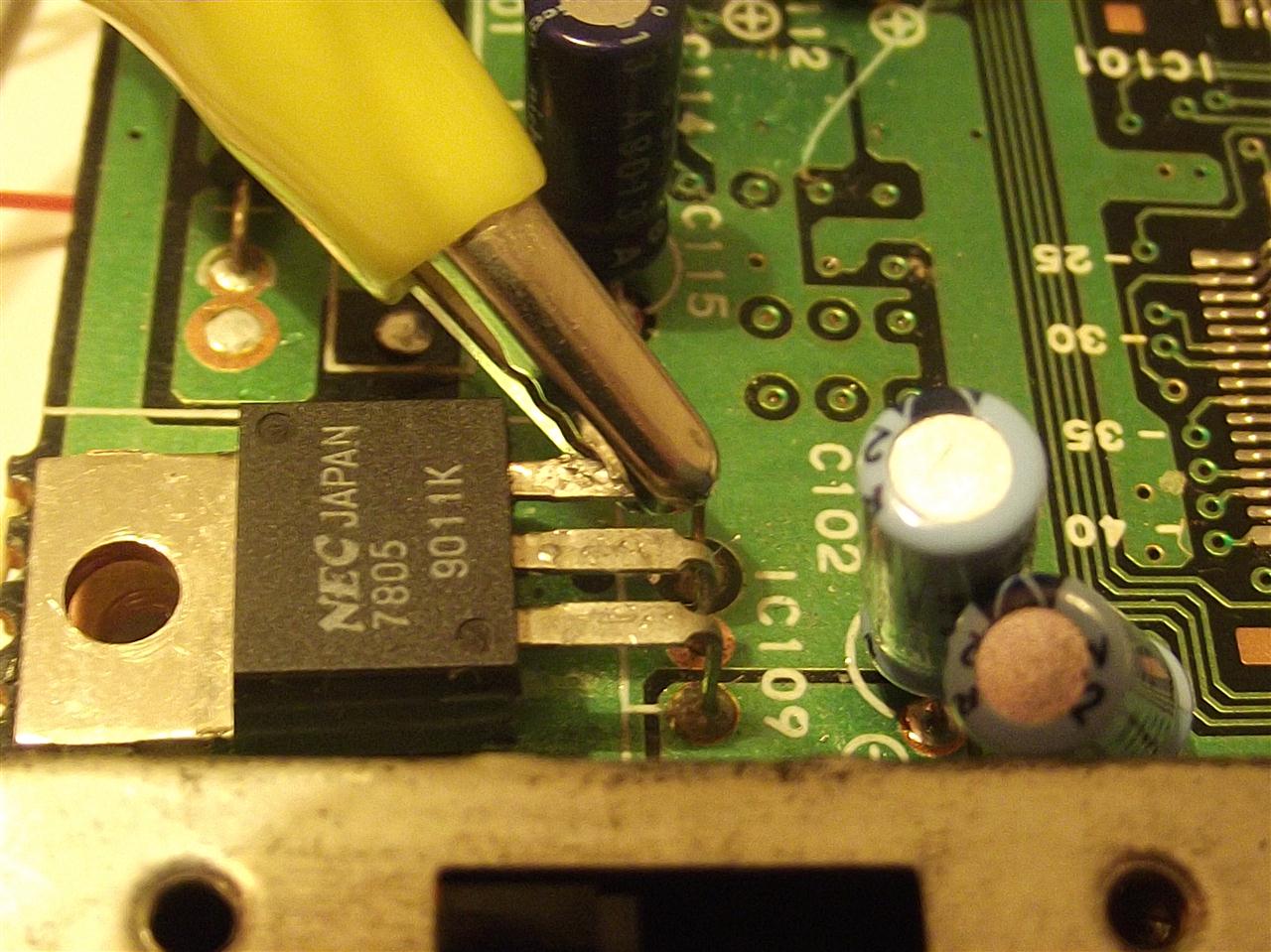
As above
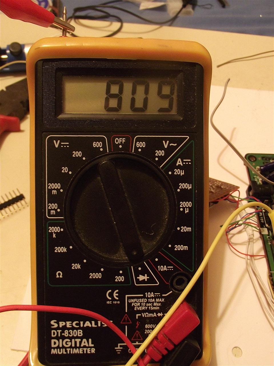
Vss /ground and leg 29 now connected to a Vss /ground point
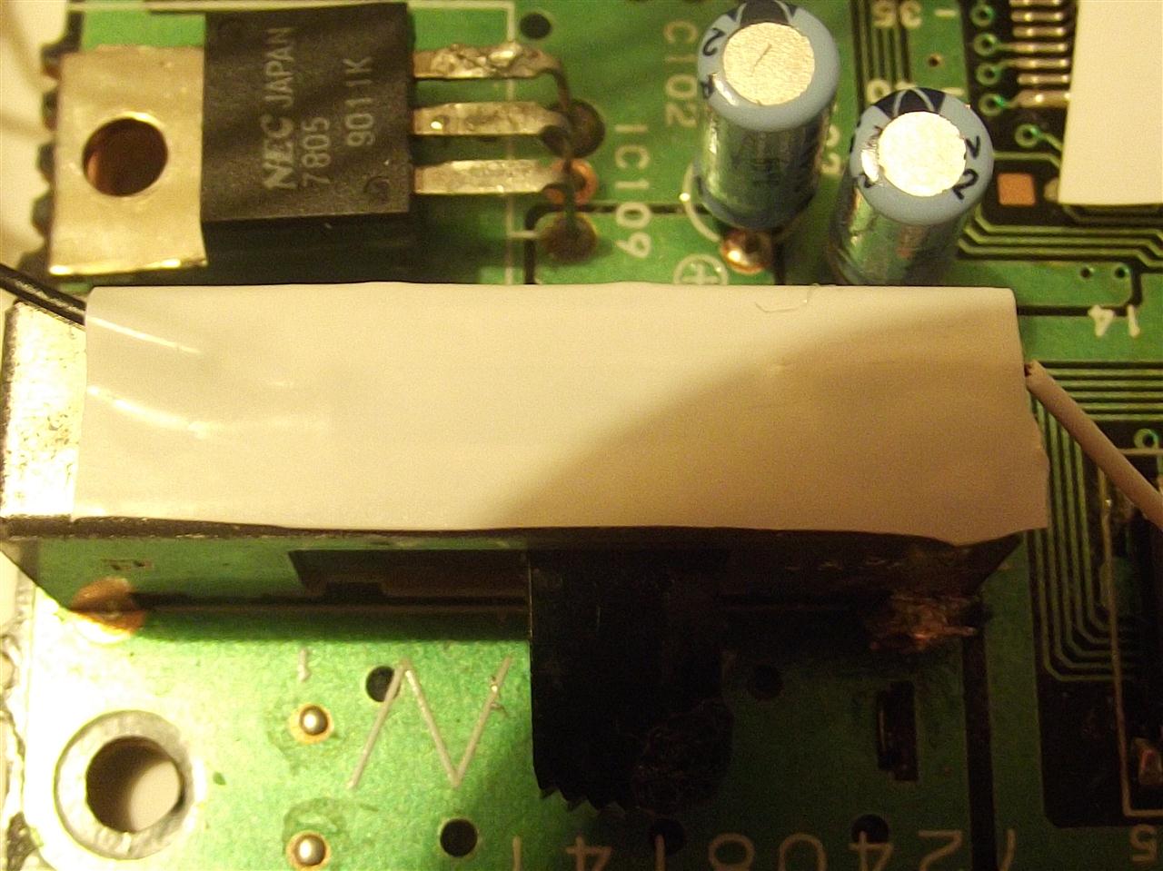
Picture in wrong order,showing insulated tape under lifted leg
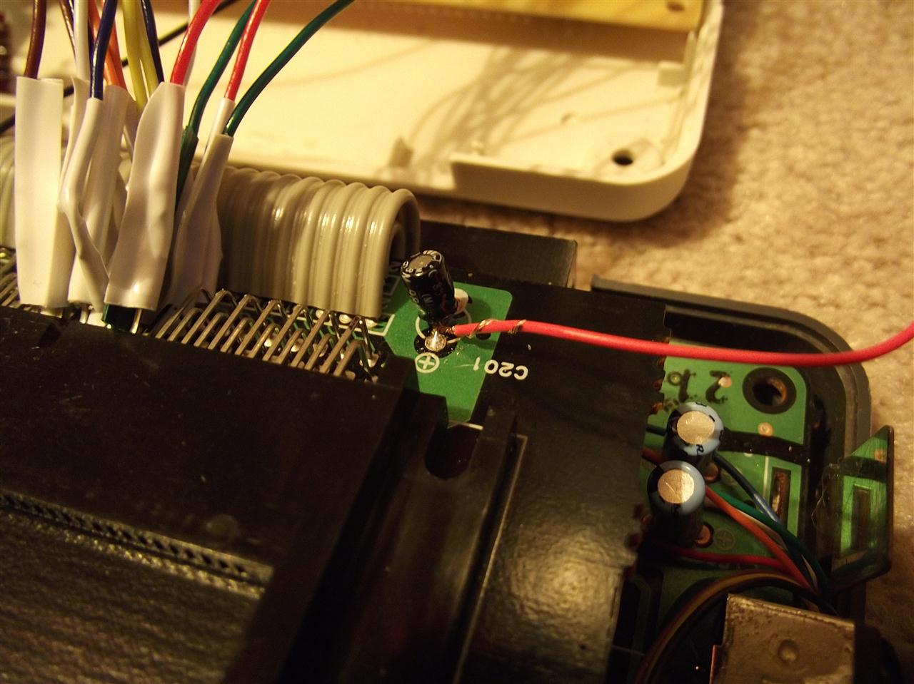
Vcc/ + 5 volt supply.Minus tape to secure it down to the pcb.
I looped the wire under and around the + 5 volt cap's Vcc / leg ,wrapped it around the wires insulation,then popped it between my thumb and forefinger and rolled it so it twisted very tightly around the cap's Vcc leg .
Remember,there's no point in using crimp terminals,stick to soldering .
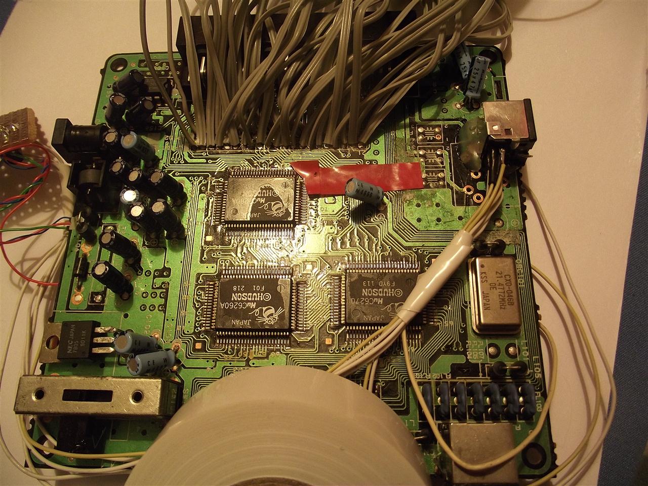
Old board,showing another point to get your Vcc/ + 5 volt connection from
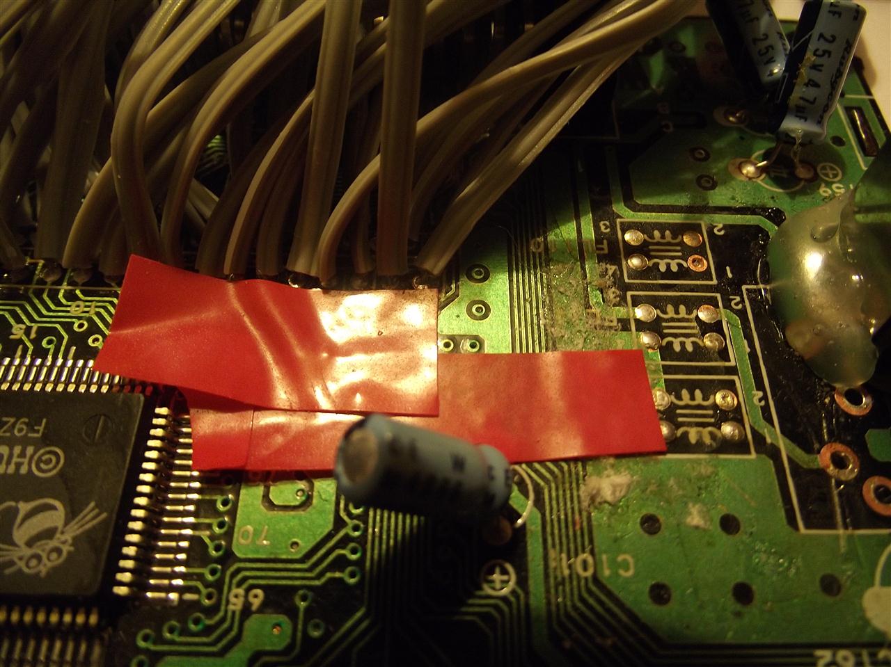
Vcc / + 5 volt can also be got from the LEFT THROUGH HOLE.
Pogo pins/test pins ? could be of use there or you can use the same size wire i used here as it fits through.
As above
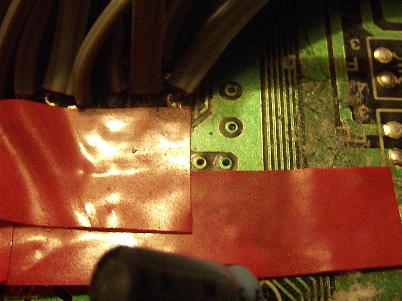
Vcc/ + 5 volt connection taped down and secure

I think that's it .Get it improved and get them available .