Ah, thanks for trying!
Alright, just to review here, I trust that the two 10K pots for the Red-Y/Blue-Y lines were set right in the middle to 5k, 5k, etc. when you started it off ? You do have to adjust those pots to achieve the proper tinting especially with a dramatic change in Luma/Y as was done here, and they're not supposed to be exactly the same actually. Strength levels are supposed to be .71 for Red-Y and .57 Blue-Y according to the spec. So, output resistance of Blue-Y would be higher in a normal design, it should be weaker than Red-Y, but in Steve's case with the 10K pot adjustments and no output resistors, you'd fiddle around with just those pots.
Another test would've been to have had just the Luma/Y output from your PCB/board connected to the TV's Composite jack to see if you're getting a good black'n'white picture - that would be the best test for a good black'n'white picture. Should be no excess green, or blue, or red, etc. Then after connecting Luma/Y normally to the YPbPr/Component jacks with Red-Y and Blue-Y also, you'd have to adjust those 10K pots for tinting.
But yeah, I assume in your test you tried plenty of adjusting of those pots and didn't just leave 'em alone, right ? I don't see you mentioning any adjusting of those, just your custom ones on the RGB input lines.
Well, anyhow, that formula was based on that company's op-amp and a sweet spot 324 Ohm feedback resistor, so no expectations it'd apply to the generic transistor with a 500 Ohm feedback resistor.
There still should be a way to compute exact resistance values for our Luma/Y, but this might not be it is all.Also I heard that there are ways to make a similar circuit with an op-amp and some resistors, ever look into this steve?
Yeah, that's what this is that I posted earlier!

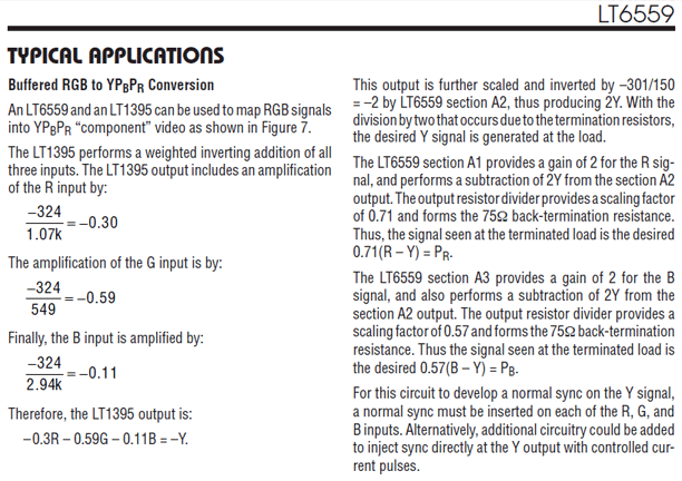
Here's where that math info I wanted to test with came from (
http://cds.linear.com/docs/en/datasheet/6559f.pdf - good research material from this PDF!):

The company's full page on their circuit titled, "High Speed RGB to YPBPR Converter":
http://www.linear.com/solutions/1312They're trying to sell you on their chips, LT6559 and LT1395, both op-amps, and that "high speed" RGB-to-YPbPr circuit is an example on how to use them.
http://www.linear.com/product/LT1395 - (Single 400MHz Current Feedback Amplifier)
http://www.linear.com/product/LT6559 - (Triple Video Amplifier)
Self Reminder: I have recently created PCE/TG-16 video testing software that I asked Bonknuts/Tom to produce for me both for flashcarts and as a CD-R for CD drives. All the software does is when it's booted is make an all white screen, all pixels max white, then every time you press button I, it goes to all Red, then all Green, and all Blue, etc. This will allow you to view a steady RGB signal when using an oscilloscope on the HuC6260 video chip on the RGB pins and hopefully help tweak circuits like this one, etc. I will update the thread's OP with info and download links later when I get a chance.