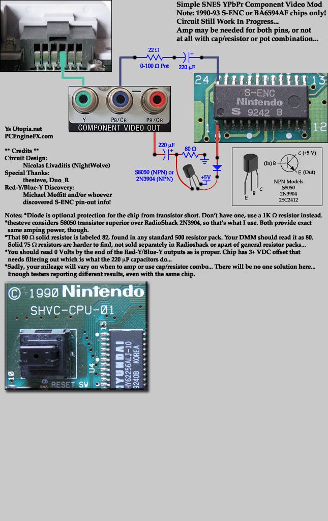
Pursuing this for me began here thanks to Duo_R. The desire to tweak and learning a few tricks from thesteve made the simple circuit design you see below possible. It only applies to 1st generation SNES consoles made between 1990-1993 with the S-ENC chip clearly shown or BA6592F. If your video chip says "S-RGB" ANYWHERE on it (
the newer SNES JR/MINI/FAT models), sorry, this mod will NOT work!
The known working chips for this are labeled as:
1) BA6592F (you'll likely need to amp both Red-Y & Blue-Y guaranteed with this chip)
2) S-ENC (you might get away with just using a cap/resistor combo on one or both signals, as I did for Blue-Y)
3) S-ENC B BA6594AF
<WIP>
(Self-Reminder: Add official circuit dumps to image, and call for EE to professionally design circuit.)

Memo: Ultimately, the purpose of the pretty schematic below is to help lead to a more perfect transistor-based amp for Red-Y and Blue-Y by allowing others to clearly see what ROHM/SNES engineers did. It's out of that hope that a professional electrical engineer (like thesteve) with a scope, SNES hardware and who IS hands-on will show up and be able to model the best circuit design by having all available information upfront and in a very clear manner, etc. That's the idea. So yeah, here's what's currently going on inside a 1990 SNES, all 100% verified:

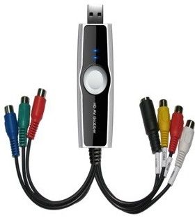
I recently bought a nice toy which has been a big help for tweaking this mod:
http://www.ebay.com/itm/120966019918?ssPageNamehttp://www.ebay.com/sch/i.html?_odkw=F03147+Capture
| |
It's a F03147 HD USB 2.0 Video Audio Capture Grabber with 240p+ YPbPr support! Yay! And $23 shipped!
I rolled the dice in buying this because I didn't know if 240p would be supported, but thankfully, it worked perfectly! So, with this device, you can take digital screenshots of videogames on your PC via analog Composite, S-Video or Component video signals, side-by-side, then page up/down very quickly on the images to see how well the color level and tint match up, etc. In other words, pause the game, switch to Composite mode, take a screenshot, switch to S-Video, take another screenshot, finally, switch to YPbPr Component, repeat, etc. Adjust your circuit as needed so that the coloring/tint matches up to the native signals (Composite/S-Video) that the system is producing for best results, etc. You get the idea.
Now, the included software is kind of cheap, but it works with any DirectShow supporting software like DScaler and any other Movie Capture software, etc. |
Extra Notes:
It's important to understand that the circuitry of a TV set that processes an analog YPbPr Component video signal varies and even if one could figure out the perfect output circuit, you're still gonna get people complaining about green levels, tint, yellow mixed colors even, etc... That's the unfortunate reality.
Examples: I have a Samsung LCD 19" TV that can process a 240p signal thankfully. It computes the color green perfectly. This is testable with Super Street Fighter II, the Ken stage where the water is supposed to be green and also with Super Mario World, the title screen. However, my old school Panasonic 32" CRT TV has a problem computing green from a Component signal and it's usually darker and/of the wrong tint, looks more bluish. Yet on the very same TV set, the circuitry for Composite/S-Video properly displays green as it should be! Two different sets+capture device, same circuit on console, yet green is wrong in one, the CRT. :\
The other issue is how it handles red, apparently. My Component-to-USB device tells me that I need a little more amplification for red, so it's almost perfect with no output resistance, just straight from the transistor with filter cap seems right. This also holds true for my Samsung LCD. But again, this old school CRT tells me that the red is a little hot and could use a 15-25 Ohm output resistor which is why my
old first circuit had 15 Ohm resistors on the outputs... So anyhow, I am preferring to trust my USB device here in the view that a circuit revolving around that would produce the most universal result, while accepting that some TV sets you're gonna have differences and people may customize the circuit to fit that particular TV set.
Reference Links:
http://www.nintendoage.com/forum/messageview.cfm?catid=22&threadid=71069http://www.racketboy.com/forum/viewtopic.php?f=25&t=37716&start=90http://forums.nesdev.com/viewtopic.php?f=12&t=8979&p=110204#p110204 (More complex circuit with chip here)
[ I know, I know, it's a NEC forum, but doesn't mean we have to be all "platformist" exclusionary or whatever  ]
]