Author Topic: MOD GUIDE - Simple SuperNES Component (YPbPr) Video Mod [7/20/2013]  (Read 312 times)

NightWolve

  • Hero Member
  • *****
  • Posts: 5277
Pursuing this for me began here thanks to Duo_R. The desire to tweak and learning a few tricks from thesteve made the simple circuit design you see below possible. It only applies to 1st generation SNES consoles made between 1990-1993 with the S-ENC chip clearly shown or BA6592F. If your video chip says "S-RGB" ANYWHERE on it (the newer SNES JR/MINI/FAT models), sorry, this mod will NOT work!

The known working chips for this are labeled as:
1) BA6592F (you'll likely need to amp both Red-Y & Blue-Y guaranteed with this chip)
2) S-ENC (you might get away with just using a cap/resistor combo on one or both signals, as I did for Blue-Y)
3) S-ENC B BA6594AF

<WIP>
(Self-Reminder: Add official circuit dumps to image, and call for EE to professionally design circuit.)
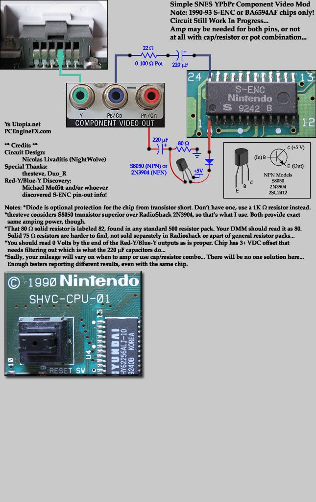

Memo: Ultimately, the purpose of the pretty schematic below is to help lead to a more perfect transistor-based amp for Red-Y and Blue-Y by allowing others to clearly see what ROHM/SNES engineers did. It's out of that hope that a professional electrical engineer (like thesteve) with a scope, SNES hardware and who IS hands-on will show up and be able to model the best circuit design by having all available information upfront and in a very clear manner, etc. That's the idea. So yeah, here's what's currently going on inside a 1990 SNES, all 100% verified:


I recently bought a nice toy which has been a big help for tweaking this mod:
http://www.ebay.com/itm/120966019918?ssPageName
http://www.ebay.com/sch/i.html?_odkw=F03147+Capture
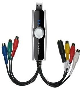
 
It's a F03147 HD USB 2.0 Video Audio Capture Grabber with 240p+ YPbPr support! Yay! And $23 shipped!

I rolled the dice in buying this because I didn't know if 240p would be supported, but thankfully, it worked perfectly! So, with this device, you can take digital screenshots of videogames on your PC via analog Composite, S-Video or Component video signals, side-by-side, then page up/down very quickly on the images to see how well the color level and tint match up, etc. In other words, pause the game, switch to Composite mode, take a screenshot, switch to S-Video, take another screenshot, finally, switch to YPbPr Component, repeat, etc. Adjust your circuit as needed so that the coloring/tint matches up to the native signals (Composite/S-Video) that the system is producing for best results, etc. You get the idea.

Now, the included software is kind of cheap, but it works with any DirectShow supporting software like DScaler and any other Movie Capture software, etc.


Extra Notes: It's important to understand that the circuitry of a TV set that processes an analog YPbPr Component video signal varies and even if one could figure out the perfect output circuit, you're still gonna get people complaining about green levels, tint, yellow mixed colors even, etc... That's the unfortunate reality.

Examples: I have a Samsung LCD 19" TV that can process a 240p signal thankfully. It computes the color green perfectly. This is testable with Super Street Fighter II, the Ken stage where the water is supposed to be green and also with Super Mario World, the title screen. However, my old school Panasonic 32" CRT TV has a problem computing green from a Component signal and it's usually darker and/of the wrong tint, looks more bluish. Yet on the very same TV set, the circuitry for Composite/S-Video properly displays green as it should be! Two different sets+capture device, same circuit on console, yet green is wrong in one, the CRT. :\

The other issue is how it handles red, apparently. My Component-to-USB device tells me that I need a little more amplification for red, so it's almost perfect with no output resistance, just straight from the transistor with filter cap seems right. This also holds true for my Samsung LCD. But again, this old school CRT tells me that the red is a little hot and could use a 15-25 Ohm output resistor which is why my old first circuit had 15 Ohm resistors on the outputs... So anyhow, I am preferring to trust my USB device here in the view that a circuit revolving around that would produce the most universal result, while accepting that some TV sets you're gonna have differences and people may customize the circuit to fit that particular TV set.


Reference Links:
http://www.nintendoage.com/forum/messageview.cfm?catid=22&threadid=71069
http://www.racketboy.com/forum/viewtopic.php?f=25&t=37716&start=90
http://forums.nesdev.com/viewtopic.php?f=12&t=8979&p=110204#p110204 (More complex circuit with chip here)

[ I know, I know, it's a NEC forum, but doesn't mean we have to be all "platformist" exclusionary or whatever ;) ]
« Last Edit: February 08, 2014, 06:40:02 PM by NightWolve »

burn_654

  • Full Member
  • ***
  • Posts: 130
Re: MOD GUIDE - Simple SuperNES Component (YPbPr) Video Mod [3/27/2013]
« Reply #1 on: March 27, 2013, 08:40:22 AM »
I've done a variation of this mod on a BA6592F equipped snes...even built a standalone RGB to Component box using that chip. (there's a great thread on sega-16...on a Nintendo console, no less) But there are a few differences...I've used transistors (2n3904's in this case) on both Pb and Pr, but straight Y like you have. I'm actually toying with adding some resistance to Y on my tv set.

S-ENC marked chips already have some built-in amplification on Pb and Pr, I've read - they're an altered BA6592F. But BA6592F snes's are usable in a similar way (Pb and Pr will need transistor amps) so this is a great mod to talk about!
« Last Edit: March 27, 2013, 08:44:25 AM by burn_654 »
Quote from: RegalSin
You know for that r-tard who goes like "oh something retro, let me put down my vabagelina, stop drinking my cheeze wine, and get to playing".

fsa

  • Full Member
  • ***
  • Posts: 136
Re: MOD GUIDE - Simple SuperNES Component (YPbPr) Video Mod [3/27/2013]
« Reply #2 on: March 27, 2013, 12:08:40 PM »
Can something like this be done on the SNES with the following chip, BA6594F, I did some research and did see someone connect direct to plug.
Looking for TG16 games I don't have already.

NightWolve

  • Hero Member
  • *****
  • Posts: 5277
Re: MOD GUIDE - Simple SuperNES Component (YPbPr) Video Mod [3/27/2013]
« Reply #3 on: March 27, 2013, 12:47:06 PM »
Yeap, *IF* you have the other S-ENC B chip that says BA6594AF. I read that neither signals need any amplification from that one, but I can't confirm it. Notice that my chip is different, just says "S-ENC" and it's the first model that Nintendo used. Since I don't have a SNES unit with your chip, I can't tell you what the resistances would be so I didn't mention it just yet in this thread, but what I CAN tell you is that those guys that wired them up to the pins directly are dangerous/lazy/uninformed! There's some kind of DC voltage (3+ Volts) and no filter capacitor + resistor was used!!! So, you got 3+ Volts DC coming out of RCA jacks/wires... Not good, really... If your unit is off let's say and you're connecting cables to these jacks with static build up, you touch the tip of the male end of the cable as you're connecting it to the TV, you'd send a static charge right into that chip, so not good either...

Try just using a 220 uF cap from input pins 1+24 to output RCA jacks for Red-Y/Blue-Y! Just like I did in my schematic for my chip for Blue-Y, minus the resistor! If you see that the signal is too strong, you'll have to play around to find the best resistor yourself afterwards. Better yet, buy a 3 pack of 100 Ohm potentiometers!! Too much variance, my results are likely not gonna apply to you. Luma/Y from the Multi-AV out is rocksolid, so that's no problem to tap it directly as shown in my Mod Guide image.
« Last Edit: March 29, 2013, 06:44:05 PM by NightWolve »

fsa

  • Full Member
  • ***
  • Posts: 136
Re: MOD GUIDE - Simple SuperNES Component (YPbPr) Video Mod [3/27/2013]
« Reply #4 on: March 27, 2013, 03:34:55 PM »
Thanks NightWolve, I wanted to get others feedback as all the other video mod I have come across has some sort of cap or resistor. I will post back when I get it done and tested based on you feedback with the caps.
Looking for TG16 games I don't have already.

NightWolve

  • Hero Member
  • *****
  • Posts: 5277
Re: MOD GUIDE - Simple SuperNES Component (YPbPr) Video Mod [3/30/2013]
« Reply #5 on: March 30, 2013, 01:06:44 AM »
Some quicki screenshots using my USB YPbPr capture device with the latest circuit. Chose to just recommend a 0-100 Ohm pot on the outputs because determining the best value is tricky and given what Mike Moffitt said about the Red-Y/Blue-Y imbalances, which was true for me (my case of not having to amplify Blue-Y), the results for what's "best" is gonna be all over the friggin' place, even for the exact same chip and board revision, etc. That's really too bad. It's still an interesting mod and all, I've enjoyed the time spent fiddling around with it.


In the SSFII case below, I took a screenshot with ZSNES and resized it to match the YPbPr shot. That green water there actually is a good test to see if your TV's circuitry is properly decoding green. My CRT doesn't handle it well; it'll come out bluish while it'll be perfect on my modern Samsung LCD 720p TV which supports 240p signals. Another thing, I turned up the sharpness a bit on my capture device's settings, so that's why it's mismatched compared to the ZSNES shot. Anyhow, pretty good on that one! Red seems alright, green is decoded proper by the device... Yellow though is an issue, not as strong as it should be (not judged from this screenshot), others report the same (weak yellow issue) with other types of circuits... But, eh, not bad for a poor man's generic transistor amp and only having to do it on one line in my case!


Below is what that green looks like on my old school Panasonic 32" CRT 1999 era. It's "cool," doesn't have that fluorescent appearance that my Samsung 19" LCD has, nor the USB device or ZSNES. However, if you switch to S-Video/Composite, it works, so this is strictly a matter of the circuitry that processes the YPbPr signal.


I wish I hadn't done the +5V mod to my system though. Some time back, my +5V regulator burned out and I decided that since I had a good, well-regulated +5V 3A power supply, I should try to mod the system to work with it, then I could get rid of that big heat sink metal that covers the relevant work area with the chip, plus it'd be better for the system... Well, I succeeded with some hiccups at first, but yeah, I didn't have to order a new regulator which I didn't wanna have to do... Anyhow, I wonder if that change affects my results in terms of signal strength levels and so forth, so I kinda wish I hadn't done it now... So yeah, it's a +5V modded SNES in action here: I had to remove a few caps in the power area near the power switch, added clips for a 1A glass fuse (burned a few), had to bridge two traces and connect the input to output holes/solder-points where the regulator was together, obviously. Poor thing is still working. ;)
« Last Edit: April 01, 2013, 12:26:48 AM by NightWolve »

turbokon

  • Hero Member
  • *****
  • Posts: 2181
Re: MOD GUIDE - Simple SuperNES Component (YPbPr) Video Mod [3/30/2013]
« Reply #6 on: March 30, 2013, 07:10:23 AM »
Thanks for taking the time to post this, definitely a project for me eventually:)
Turbo fan since 1991 after owning my first system.

Check out my website:)
www.tg16pcemods.com

SNKNostalgia

  • Hero Member
  • *****
  • Posts: 556
Re: MOD GUIDE - Simple SuperNES Component (YPbPr) Video Mod [3/30/2013]
« Reply #7 on: March 31, 2013, 12:05:17 PM »
For your CRT, have tried looking up the service menu codes??? I always mess with mine on my Sony Trinitron WEGA 27". They tend to have a "red push" (makes your blacks look red-brown) and mine was over-scanned vertically and shifted to the right by 8-10% in my case... so I adjusted the RDRV and RCUT to lower the "red push", and messed with VSIZ, HSIZ, HPOS and SCRLL (vertical position - better adjust). Now, I only have to mess with the geometry depending on the console and certain games with off centered picture.

Anywho, in your case, you would just have to lower the blue and push the green a bit. Remember, red and green has yellow in between, lol.

BTW, my chip says S-RGB in a later model 1 SNES. So what does that make it???

NightWolve

  • Hero Member
  • *****
  • Posts: 5277
Re: MOD GUIDE - Simple SuperNES Component (YPbPr) Video Mod [3/30/2013]
« Reply #8 on: March 31, 2013, 12:15:02 PM »
BTW, my chip says S-RGB in a later model 1 SNES. So what does that make it???


Makes it no dice for you... :( With those chips they got rid of the external output of Red-Y/Blue-Y to mix back in for Composite/S-Video production. Your options are the usual route of an external board (like JROK) for RGB-to-Component conversion or a guy called Ace who has been making circuits around this BA7230LS chip that he likes. You don't even have S-Video for those I hear, eh ?? Well, here's a link to his work:

http://www.sega-16.com/forum/showthread.php?22237-New-RGB-to-Component-converter-design-using-the-BA7230LS&p=518344&viewfull=1#post518344

SNKNostalgia

  • Hero Member
  • *****
  • Posts: 556
Re: MOD GUIDE - Simple SuperNES Component (YPbPr) Video Mod [3/30/2013]
« Reply #9 on: April 02, 2013, 12:18:17 PM »
It puts out S-Video fine and the S-RGB chip says BA6592F on it. Should be fine right??? It is a later model SNES, but not the last ones they made just before SNES Jr. BTW, this particular SNES doesn't have the faint vertical bar running down the middle of the screen either. So this might be an oddball out of the SNES???

NightWolve

  • Hero Member
  • *****
  • Posts: 5277
Re: MOD GUIDE - Simple SuperNES Component (YPbPr) Video Mod [3/30/2013]
« Reply #10 on: April 03, 2013, 04:35:20 AM »
Check again. It likely says S-RGB BA6595F. That chip gives you good S-Video and RGB output. If it was a BA6592F, found on 1990 models, there wouldn't be a S-RGB label anywhere. This links deals with the known chips: http://nfggames.com/forum2/index.php?topic=3525.0
« Last Edit: February 08, 2014, 06:35:10 PM by NightWolve »