Author Topic: S-Video mod with lots of photos! Also, a little help needed..  (Read 485 times)

chipperkwah

  • Newbie
  • *
  • Posts: 29
Alright! just got my Duo R apart to start the mod. However, I ran into a little issue right away. My board looks different than other boards I've seen in the pictures people posted of their s-vid mods. I was going to cut the R130 resistor and solder in a switch so that I can keep composite support. In the photos I've seen, the resistor is through-hole and right next to the HuC6260 chip. On my board, all the resistors are surface mount and the R130 resistor is far away from the C6260 chip and on the bottom of the board. If one of you guys can point me in the right direction that would be awesome, and I can get this sucker done. I took some pics.

Here's my C6260 chip.


And here's the bottom of my board, where I found the R130


If anyone can tell me where I need to solder to get chroma I will be eternally grateful.
« Last Edit: June 15, 2013, 05:34:05 PM by chipperkwah »

ApolloBoy

  • Sr. Member
  • ****
  • Posts: 477
Re: S-Video mod with lots of photos! Also, a little help needed..
« Reply #1 on: June 15, 2013, 07:48:35 PM »
Just use composite video for your chroma, put it through a 0.001 uF cap and bang, you've got chroma.
Quote from: Arkhan
it makes me laugh because people are like I REMEMBER PLAYIN THAT BACK IN THE DAY, MAN THAT WAS FUN.

and then I go "yeah I remember playing that 2 days ago because I still have my SNES, retard"

chipperkwah

  • Newbie
  • *
  • Posts: 29
Re: S-Video mod with lots of photos! Also, a little help needed..
« Reply #2 on: June 16, 2013, 03:52:50 AM »
Just use composite video for your chroma, put it through a 0.001 uF cap and bang, you've got chroma.

I'm aware that this method exists, but I'm wanting to do it the other way. Thanks for your reply though!

NightWolve

  • Hero Member
  • *****
  • Posts: 5277
Re: S-Video mod with lots of photos! Also, a little help needed..
« Reply #3 on: June 16, 2013, 06:41:17 AM »
You've come to the right place, chipper! One mod suggestion coming right up! ;) This should work out perfectly, unless there's another trace underneath the chip for pin 40 there going elsewhere (which I highly doubt) so you'll have to see. If you follow that resistor you wanted to break off to the 'via' with a continuity test, you'll know you're good from the get-go.
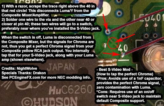


I think that pretty much covers my idea on how to do this. Was never fond of Drakon's way of breaking off a resistor and just leaving default Composite support broken, but the idea for obtaining a perfect Chroma was a good one and with a switch, nothing has to break, etc.

Oh, and in case you haven't seen it:
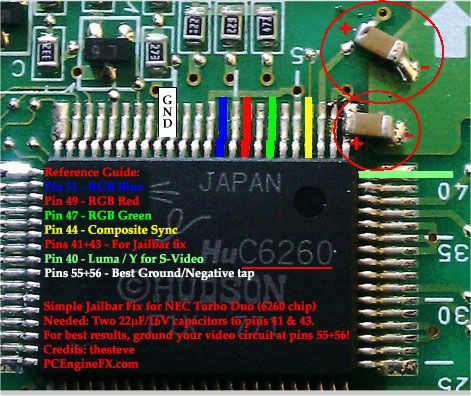


Just to note, pin 40 is our Luma. And you know what ?? Maybe go ahead and use pin 55+56 for the grounding of your S-Video jack. For a RGB amp or YPbPr mixer, that's the best place to tap ground to potentially reduce jailbars (a steve suggestion). While that problem is not very apparent for S-Video to my knowledge, it's probably just good practice to ground there anyway I suppose. So FYI.

Just use composite video for your chroma, put it through a 0.001 uF cap and bang, you've got chroma.


Most will do it the simple way obviously, but if you want the best, now we know how. One modder noted in Professor's S-Video thread that he happened to have a TV/monitor that didn't like the Chroma filtered straight from a Composite tap with a 1 nF capacitor, so in rares cases, this will cover that issue. I'm doing it this way simply because if the "best way" is available, and it's not that difficult, I'm gonna prefer the best for my one and only system.
« Last Edit: June 16, 2013, 07:08:41 AM by NightWolve »

chipperkwah

  • Newbie
  • *
  • Posts: 29
Re: S-Video mod with lots of photos! Also, a little help needed..
« Reply #4 on: June 16, 2013, 07:38:16 AM »
edit: So once I've cut the trace and soldered in my switch, the best place to tap for chroma would just be the AV jack? Just making sure I'm understanding everything correctly.

NightWolve, I had a feeling you would come through with the goods. I really appreciate the help. So, I've hooked my amp up to pin 40 and tapped 5v according to the guide here: http://www.pcenginefx.com/forums/index.php?topic=13044.0

Here are a few more pictures. When I get home from work and finish it up I'll take a couple more.

Pin 40. Thought it might be a little iffy getting this tacked down without bridging any pins, but I tinned the wire and all it took was a tap with the iron, really solid connection.


S-Video jack. Drilling this made me a little nervous but I just used a nice 7/16 bit and all was well. If anyone is looking to use this jack I found it here http://console5.com/store/parts/av-jacks/s-video-jack-gold.html. It's a really nice part.


5V tapped from the AV port.


« Last Edit: June 16, 2013, 08:01:30 AM by chipperkwah »

NightWolve

  • Hero Member
  • *****
  • Posts: 5277
Re: S-Video mod with lots of photos! Also, a little help needed..
« Reply #5 on: June 16, 2013, 08:31:23 AM »
edit: So once I've cut the trace and soldered in my switch, the best place to tap for chroma would just be the AV jack?


Exactly, just like the full S-Video guide, just that now you don't need a capacitor. Your switch stays in the off position, the internal Composite Mixer/Amp is only being fed Red-Y, Blue-Y and Chroma Burst, so that leaves only a perfectly amplified Chroma signal at the output end. If you ever need to go back to Composite, flip the switch, and back to normal. New TVs are phasing out S-Video, so you don't see it as much as you used to. You'll find Composite/Component and on to the digital age with HDMI, etc.

http://console5.com/store/parts/av-jacks/s-video-jack-gold.html

I like this jack BTW. I hate the one that I bought. I almost got screwed on the shipping cost ($9 bucks) and it didn't even include the a hexagonal nut to tighten the damn thing!! I actually had to make my own from a plumbing-related type nut normally used to tighten a 3/8" compression fitting down. It was the only thing I could find that had the proper metric size and threading...

Quote
NightWolve, I had a feeling you would come through with the goods. I really appreciate the help.


You're very welcome!! I'm a people-pleaser, what can I say, ya know ??? ^_^

Photos look good, can't wait to see how it works out! :) Think about the grounding suggestion with pins 55+56 though. You can bridge them together, so it's easy to solder one wire inbetween since it can be done to both pins.
« Last Edit: June 16, 2013, 12:30:18 PM by NightWolve »

chipperkwah

  • Newbie
  • *
  • Posts: 29
Re: S-Video mod with lots of photos! Also, a little help needed..
« Reply #6 on: June 16, 2013, 09:03:14 AM »
edit: So once I've cut the trace and soldered in my switch, the best place to tap for chroma would just be the AV jack?

Exactly, just like the full S-Video guide, just that now you don't need a capacitor. Your switch stays in the off position, the internal Composite Mixer/Amp is only being fed Red-Y, Blue-Y and Chroma Burst, so that leaves only a perfectly amplified Chroma signal at the output end. If you ever need to go back to Composite, flip the switch, and back to normal. New TVs are phasing out S-Video, so you don't see it as much as you used to. You'll find Composite/Component and on to the digital age with HDMI, etc.

Perfect, the only thing left to do is cut the trace and tap chroma and ground. I forgot to order a switch, so I'll wire up the trace from pin 40 and the via and tape the wires up in a little bundle until I have a chance to order a switch and drill a hole. I'll post pictures of how it looks on my PVM. Composite already looked pretty decent, so I'm sure it will be very nice.

Tatsujin

  • Hero Member
  • *****
  • Posts: 12311
Re: S-Video mod with lots of photos! Also, a little help needed..
« Reply #7 on: June 16, 2013, 03:33:58 PM »
So if I get this thing right, this is not the S-Vid mod that requires an add. RGB to S-Vid decoder right?

How does the outcome of this mod compare to a mod with extra decoder?
www.pcedaisakusen.net
the home of your individual PC Engine collection!!
PCE Games coundown: 690/737 (47 to go or 93.6% clear)
PCE Shmups countdown: 111/111 (all clear!!)
Sega does what Nintendon't, but only NEC does better than both together!^^

NightWolve

  • Hero Member
  • *****
  • Posts: 5277
Re: S-Video mod with lots of photos! Also, a little help needed..
« Reply #8 on: June 17, 2013, 05:00:01 AM »
So if I get this thing right, this is not the S-Vid mod that requires an add. RGB to S-Vid decoder right?


Correct, it's native; in order to produce the basic Composite signal, a video chip has to internally produce Luma and Chroma and mix them. NEC could've provided access to these signals via a S-Video cable, but all they did is Composite... They could've, I mean, SNES had S-Video in 1990, but either they were cheap or it was just right at the point before S-Video was taking off. Still, Turbo Duo was a later redesign in the 90's, that should've had it I think... Cheaper than having the little stereo headphone jack and amplifier accessible I'd bet...

So yeah, pin 40 off of that 6260 chip is the accessible Luma/Y that is sent into the native Composite Mixer/Amplifier. There are 3 other signals mixed to produce the Chroma: Red-Y, Blue-Y and Chroma Burst. You can see the whole circuit from this post by Bonknuts. The idea about what chipper's doing comes from there, you disconnect the Y (Luma), and only the other 3 signals are going in, so at the end you get only a perfectly amplified Chroma.

Quote
How does the outcome of this mod compare to a mod with extra decoder?


It's the best. A custom external mixer/encoder could never be as good or as accurate. I think more so in NEC's case given what Bonknuts has said in the past about the RGB going through a color space conversion internally before being outputted by the 6260 chip. The RGB output pins on this chip are *not* converted, but the Luma/Y and Chroma will have gone through this conversion inside the chip, so they're gonna be more accurate color-wise. So goes the theory if true.

The key overall is Luma/Y as to why it's the best. Recall that the JROK encoder doesn't work and the creator wasn't sure if his $10 Sync Cleaner would help... One of the tricky things is mixing signals to produce Luma/Y properly which requires RGB + Composite H/V Sync. If you don't mix the Sync just right, it won't work on some TVs/monitors (no picture). Point is, the Luma/Y from pin 40, right off the chip and after simple transistor amplification, is far more trustworthy than anybody else's custom mixing where they're playing around with RGB + Sync (even steve with his YPbPr mixer circuit). You have to assume that the Hudson/NEC engineers did the best possible job and that's what you'd be competing against.
« Last Edit: June 17, 2013, 05:11:54 AM by NightWolve »

chipperkwah

  • Newbie
  • *
  • Posts: 29
Re: S-Video mod with lots of photos! Also, a little help needed..
« Reply #9 on: June 18, 2013, 11:40:29 AM »
Well, got everything wired up last night but something is up. I'm just getting a rolling b&w picture. Sometime this week I'll pull the whole thing and do it over, double triple checking all my connections.

NightWolve

  • Hero Member
  • *****
  • Posts: 5277
Re: S-Video mod with lots of photos! Also, a little help needed..
« Reply #10 on: June 18, 2013, 02:37:06 PM »
If you amplified the Luma correctly and connected it to the right pin on the S-Video jack, you should be getting a perfect black'n'white picture. Where many mess up is with the right and left transistor leads (power versus output). The middle lead is the signal input, so that's easy enough, but make sure the +5 V and the signal output were hooked up correctly. When facing the flat side of the transistor, the right pin is the power. Here's another guide I made to illustrate it.

No color would be due to no Chroma signal hooked up at all, but sounds like you have syncing issues, so you got a problem with the Luma to fix first. Even if you connected the Composite directly with no cap or what we're trying here, you still would get color, just wouldn't blend in as good and it's known that this idea works since Drakon and a recent modder did it who reported it was the only way it'd work on his monitor/TV. If that pin 40 trace led right to the resistor that they broke off, then you should be good on that front.

chipperkwah

  • Newbie
  • *
  • Posts: 29
Re: S-Video mod with lots of photos! Also, a little help needed..
« Reply #11 on: June 19, 2013, 07:19:37 AM »
If you amplified the Luma correctly and connected it to the right pin on the S-Video jack, you should be getting a perfect black'n'white picture. Where many mess up is with the right and left transistor leads (power versus output). The middle lead is the signal input, so that's easy enough, but make sure the +5 V and the signal output were hooked up correctly. When facing the flat side of the transistor, the right pin is the power. Here's another guide I made to illustrate it.

No color would be due to no Chroma signal hooked up at all, but sounds like you have syncing issues, so you got a problem with the Luma to fix first. Even if you connected the Composite directly with no cap or what we're trying here, you still would get color, just wouldn't blend in as good and it's known that this idea works since Drakon and a recent modder did it who reported it was the only way it'd work on his monitor/TV. If that pin 40 trace led right to the resistor that they broke off, then you should be good on that front.


Totally, thanks for all the help dude. I must have just hooked something up incorrectly to the transistor or have a cold joint somewhere. I used all black kynar so it's way too easy to lose track of what's what. I'll pull it apart and wire it back up in a few days after I visit my family. The monitor I'm using is a Sony PVM-14M4U HR, so I'm sure that the issue lies with my wiring rather than the monitor not being able to lock sync. I'll make sure to post as soon as I get it resolved, shouldn't take more than a few minutes now that I know exactly where everything is going.

P.S. I ordered the black plastic s-video jack from digikey that I had talked about in the other s-video thread as a back-up when I was getting some other parts. It came with the nut, but just to be safe I ordered an extra nut. I'm not using it, so if you need one I can throw it in an envelope and send it your way. I know you had mentioned that you had to rig up another nut to work, but if you want it to be extra clean just let me know so I can get it to you.

NightWolve

  • Hero Member
  • *****
  • Posts: 5277
Re: S-Video mod with lots of photos! Also, a little help needed..
« Reply #12 on: July 20, 2013, 08:02:27 AM »
Hey chipperkwah, what happened with this ? Looks like a month already went by, and you left us all in agony wondering if you succeeded with this or not! ;)

chipperkwah

  • Newbie
  • *
  • Posts: 29
Re: S-Video mod with lots of photos! Also, a little help needed..
« Reply #13 on: April 25, 2014, 04:27:19 PM »
Just got my duo out of storage, got new parts, and tried this mod again. Everything is DEFINITELY wired up properly, but if only luma is connected I get a blurry black and white image that rolls after a while. Could it be that I am using the SS8050 instead of the 2n3904? I know they are similar but I've double checked everything and I can't think of anything else. My monitor is working properly with s-video from my saturn, and I reconnected the cut trace temporarily to make sure that composite was still working properly. It was.