Author Topic: REPAIR GUIDE - TurboExpress: Sound Fix  (Read 8271 times)

nat

  • Hero Member
  • *****
  • Posts: 7085
Re: BIG NEWS: Turbo Express SOUND FIX!!!!
« Reply #45 on: April 24, 2008, 05:23:55 PM »
Replace both the 100uf capacitors in that cluster to equalize the volume for both channels.

nat

  • Hero Member
  • *****
  • Posts: 7085
Re: BIG NEWS: Turbo Express SOUND FIX!!!!
« Reply #46 on: July 02, 2008, 06:55:45 AM »
I want to add something here.

Sometimes replacing the two 100uf caps doesn't completely fix the audio in these units. You also need to replace the two 33uf caps in sequence with them.

The one problem here is that 33uf caps are kind of hard to find, save for special ordering them online.

I did some testing and 47uf caps work 100% as a suitable replacement (and are much more common), and actually result in a louder sound volume than using 33's.  :!:

By replacing the 4 caps (2 100's, 2 33/47's) in the sound circuit, you will restore audio functionality to 100% unless you have a bad speaker. Also, both sound channels will be equalized over the headphones so D-Lite's shunt pictured on page 1 isn't necessary.

Vanquish

  • Jr. Member
  • **
  • Posts: 83
Re: BIG NEWS: Turbo Express SOUND FIX!!!!
« Reply #47 on: August 06, 2008, 01:53:52 AM »
Hey! This is great. Just wanted to say thanks and CONGRATULATIONS!!!   :D

Duo_R

  • Hero Member
  • *****
  • Posts: 3302
Re: BIG NEWS: Turbo Express SOUND FIX!!!!
« Reply #48 on: September 12, 2008, 09:24:33 PM »
Well - I performed the Audio and Video cap mod today....and I brought a Turbo Express back to life (both were bad).....am I hero? No. Did I save a life? Yes a Turbo Express! You know who is a real hero? Hiro from Heroes.
« Last Edit: September 12, 2008, 09:26:18 PM by Duo_R »
Add my YouTube channel:


For sale trade list: http://tinyurl.com/2csm7kq

Ratix

  • Jr. Member
  • **
  • Posts: 87
Re: BIG NEWS: Turbo Express SOUND FIX!!!!
« Reply #49 on: September 13, 2008, 07:18:03 AM »
so this is what you did last night >.> i sold both my TE's a very long time ago because of that sound issue i feel like a fool for soing it to because i got ripped off when i sold them.

Duo_R

  • Hero Member
  • *****
  • Posts: 3302
Re: BIG NEWS: Turbo Express SOUND FIX!!!!
« Reply #50 on: September 13, 2008, 01:03:05 PM »
Yes - I did it last night. It would have only been a 30 minute job but I saw some other caps that looked bad and I can't walk away without replacing. So it was a TE that had no sound and no video....and here it is now:


Video works, the sound is nice and LOUD both using the internal speaker and headphones.

Now I used a different technique than D-Lite, I like making things more similar to how they were when new, so I didn't use any wires to relocate the caps. I can post pictures if you guys want. I tried getting smaller caps (if any of you live near a Fry's this is the way to go) and in some cases got creative and mounted the caps more horizontally if space was an issue. Took lots of pics during the install, and I also have a technique on remove the original caps. I call it the "lift technique" and can describe in more detail if it is helpful. I will probably post this info up on my website (needs something new on it anyway).

Well - TE sweetness. There is a ton of room to work with in some areas on the TE. The first thing I am kicking around is getting a rechargable battery pack and plug so you wouldn't never have to swap batteries out again. If I could get a pack that is smaller than the 6 AAA's, then that would give some room for other projects. Here are a couple of ideas I have for this unit:

* built-in rechargeable pack
* upgrade to a 3-3.5" screen
* built-in memory unit (ala Turbo Booster Plus)
* RGB Out
* Controller port

Of course the purists would yell at me for considering this, but I can't help it. I figure if I bring something back from the dead I have a say on what to do with it (my Frankenstein theory).

So here is where I need some help:

donations of broken controllers, multitaps (so I can get controller ports and cables)
A Turbobooster that is no longer needed or allow me to "borrow" (I need to know what consists of the memory module and see if we can somehow shrink that down to fit)
Suggestion for an RGB screen (does Ben Heck just steal from portable TV's?) - the PS1 is too big
I don't want to do any external modification on the screen, I just want to fit on the inside with a larger screen. 3.5 is more realistic.

Now I haven't played this system in say 15 years, does the LCD sometimes carry ghost images? I remember being blown away by this system (and it is still nice) but of course having a PSP you really can't get better quality LCD these days. I somehow want to bring the screen up to date (and dead pixels aren't as much of an issue anymore).

But would you describe the LCD to be a little grainy, ghosty?

Well I want to make it look as good as it does on my PS1 LCD screen (looks killer).


« Last Edit: September 14, 2008, 08:17:36 AM by Duo_R »
Add my YouTube channel:


For sale trade list: http://tinyurl.com/2csm7kq

ceti alpha

  • Hero Member
  • *****
  • Posts: 3834
Re: BIG NEWS: Turbo Express SOUND FIX!!!!
« Reply #51 on: September 14, 2008, 04:47:48 AM »
Nicely done.  :clap: :mrgreen:


"Let the CAW and Mystery of a Journey Unlike Any Other Begin"

Duo_R

  • Hero Member
  • *****
  • Posts: 3302
Re: BIG NEWS: Turbo Express SOUND FIX!!!!
« Reply #52 on: September 14, 2008, 10:29:36 AM »
ok, first this is the technique I  use to remove the caps. Lift technique - you heat up one side of the SM cap, I use a little bit of solder and the iron and heat it up nicely. I then start to lift by either the use of a small jewelers screwdriver, or needlenose pliers. You just keep lifting until you can use the iron to remove all the solder connecting to the board. Be very careful, too much force and you could lift the other leg off the board.


Once you get one side disconnected, I then bend the cap back down to the original position (bending the other leg back). I then use needlenose and then twist back and forth until the other leg breaks.


Then I installed the caps again like so:


Note, I replaced both even though the guide says just one of them. Here is why -when I see a cap that doesn't look like it is in good condition, I replace it. Same theory for a mechanic, if you are already doing work and have parts taken apart, it makes sense to replace parts that might go bad soon since you already have things taken apart (well sense for your car, not for your pocketbook).

The other reason, is by removing both caps, I can install with the horizontal technique. You can see how I have one of the caps bent, this is before I bent the 2nd cap. After I looked at this picture I realized that it looks like one of the caps has the other one bent over.... :-"

Here is the final pics of the caps installed before I put the shield back on. Removing the shield isn't necessary, but wanted to peak under the hood.


You can see I also replaced the larger yellow cap - the same thing again about replacing things that look like they are going bad (leaking, etc). It is just easier to replace once for me and put back instead of opening up over and over. I put a little electrical tape since one of the caps is very close to some SMD parts. I didn't want the cap to bend a little when putting back into the housing and short something on the board. A little tape and it is taken care of.


« Last Edit: September 14, 2008, 10:41:55 AM by Duo_R »
Add my YouTube channel:


For sale trade list: http://tinyurl.com/2csm7kq

Dazz

  • Jr. Member
  • **
  • Posts: 68
Re: BIG NEWS: Turbo Express SOUND FIX!!!!
« Reply #53 on: September 25, 2008, 01:07:20 PM »
I would like this done to my Express, please PM me with price in mind.

agt_dale_cooper

  • Jr. Member
  • **
  • Posts: 64
Re: BIG NEWS: Turbo Express SOUND FIX!!!!
« Reply #54 on: November 19, 2008, 12:10:03 PM »
Did this yesterday to two Express units, both work famously now.  Used Nat's idea for the 47 (as opposed to the 33) as well, and the thing is quite loud.  Disappointed to post, however, that the subminis I used from Parts Express (47uF 10V Sub Mini Radial Capacitor, 020-1604, and 100uF 10V Sub Mini Radial Capacitor, 020-1606) were actually LARGER than the original NEC caps, and I was forced to remote mount down the sides of the PCB.  Ordered/bought subminis in an express attempt to avoid remote mount, but these didn't fit, just a bit too tall.  Commented them as such on their site.  If you're looking for parts grab the physical dimensions of these from their site and see if Digi-Key or Mouser has smaller pieces....

Duo_R

  • Hero Member
  • *****
  • Posts: 3302
Re: REPAIR GUIDE - Turbo Express: Sound Fix
« Reply #55 on: March 05, 2009, 02:21:05 PM »
Just sharing the latest and greatest, this is how I am replacing these now (the whole audio circuit). You can fit two caps on the top of the audio jack port. And you can see where I am tucking the other two. I use a little hot glue to hold the cap on the left and use a little shrink tubing on it.


« Last Edit: March 05, 2009, 02:30:43 PM by Duo_R »
Add my YouTube channel:


For sale trade list: http://tinyurl.com/2csm7kq

Turbo D

  • Hero Member
  • *****
  • Posts: 3989
Re: REPAIR GUIDE - TurboExpress: Sound Fix
« Reply #56 on: March 15, 2009, 10:07:43 PM »
Hello fellow PCEFXers!,

Did you replace all of the capacitors in the audio amp on your TE only to be slapped in the face with a 60-cycle hum coming out of your speaker? Do you need a solution? Then look no further! Pictured below is a capacitor worth replacing if you are experiencing a 60-cycle hum out of your speaker after you have replaced all of the capacitors in the audio amp. The capacitor is 100μF 6v and is located under the shielding.


turbo D's Quick tips!:

Quick tip 1:
60-cycle hum is usually caused by a bad capacitor and/or ground!

Quick tip 2
:
When installing a new capacitor, it is okay if the voltage rating is higher than the original capacitor as long as the microfarads (μF or MFD) rating is the same. This is because the voltage rating of the capacitor is a limit not a requirement. However, you cannot replace your capacitor with one having a lower voltage rating. Also, a capacitor with a higher voltage rating will theoretically last longer. Do note that the higher the voltage rating, the larger in size your capacitor will be.

Quick tip 3:
When installing a polarized capacitor, make sure you do not reverse the polarity when installing ( e.g. solder negative to positive and vise versa.) The result will be an explosion of acid! If you are unsure of which lead is positive or negative, remember this: the negative lead of the capacitor will have a strip of arrows above it. If you have a capacitor with leads coming out of both ends, then the negative lead will be the lead that the arrows are pointing to. This is because the electricity flows in to the positive and out through the negative, hence the arrows indicating flow direction. Simple!

Charlie

  • Full Member
  • ***
  • Posts: 247
Re: REPAIR GUIDE - TurboExpress: Sound Fix
« Reply #57 on: May 23, 2009, 02:07:43 PM »
Quickie here:
I see that attachments are limited to 128k, but my bmp files are like 2Meg.  What's the best way to get them posted here?

Thanks
Charlie

Turbo D

  • Hero Member
  • *****
  • Posts: 3989
Re: REPAIR GUIDE - TurboExpress: Sound Fix
« Reply #58 on: May 23, 2009, 08:55:45 PM »
I upload my pix through http://photobucket.com/. I usually re-size my pix with photoshop before uploading, but it is not required as photobucket will re-size them for you.

Charlie

  • Full Member
  • ***
  • Posts: 247
Re: REPAIR GUIDE - TurboExpress: Sound Fix
« Reply #59 on: May 24, 2009, 06:22:23 AM »
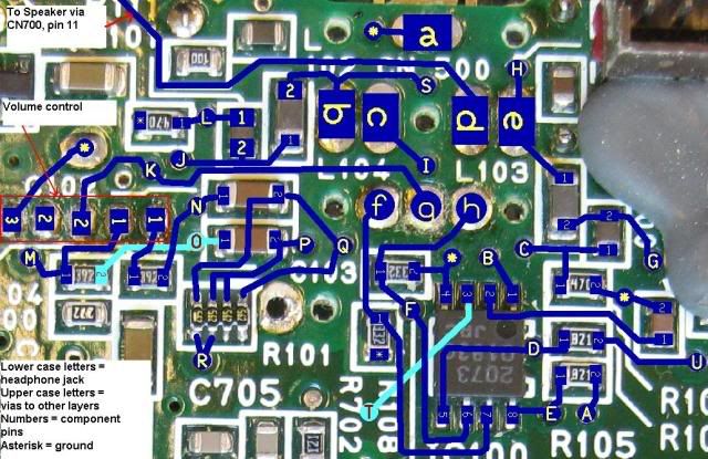
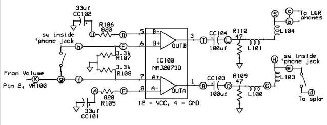
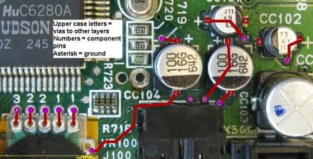
For the technically interested, the TE audio circuit and signal path explained:

Note #1: This text relates to the follow three bitmap files. 

Note #2: The quoted characters in this text represent the identical characters in the schematic, which match the identical characters
shown on the PCB pics.  The uppercase circled points in the schematic represent both the vias as shown on the circuit board pictures,
and the quoted characters given in the text below.  Likewise, the lower case circled points and text represent the
headphone jack pins.  Numeric values represent component pin numbers; an asterisk is Ground.

For speaker :
From Pin 2 of VR100, the volume control to via "K", to headphone connection "g", to headphone connection "f" (switch between "g" and "h" is open without headphones inserted), to one of two amplifier circuits (A+) in IC100 (pin 7), out pin 1 to "B", to CC103, through CC103 to "C", through L100, to "G", on to L103 to headphone connection "e".  A normally closed switch inside the connector routes the audio to "d", which routes to the speaker.

For headphones:
From Pin 2 of VR100, the volume control to via "K", to headphone connection "g", through switch to headphone connection "h" ( switch is closed when headphones are inserted), to via "F", to second of two amplifier circuits (B+) in IC100 (pin 6), out pin 3 to "T", to
CC104, to "L", through L101 and L104 to headphone connector "b" and "c", and out to both headphone speakers, giving pseudo-stereo.
Note that, when the headphones are inserted, connection "g" to "f" is NOT disconnected, thus, the speaker amplifier A+ is still active. 
Therefore, the speaker circuit is still creating an amplified signal for the speaker.  But, when the headphone is inserted, the switch
between "e" and "d" is opened, thus disconnecting the signal from the speaker.

Charlie


ABBREVIATED AUDIO CIRCUIT SCHEMATIC

TE BOARD TOP VIEW

TE BOARD BOTTOM VIEW